Heathkit HW 17 Schematic

This is the 4 pages manual for Heathkit HW 17 Schematic.
Read or download the pdf for free. If you want to contribute, please mail your pdfs to info@audioservicemanuals.com.

Page: 1 / 4
left right
Heathkit HW 17 Schematic

Extracted text from Heathkit HW 17 Schematic (Ocr-read)


Page 1

4 Bi FM
Two-Meter
Transceiver and
Mobile
Power Supply

Encrsu
H A U C :7.

Km;

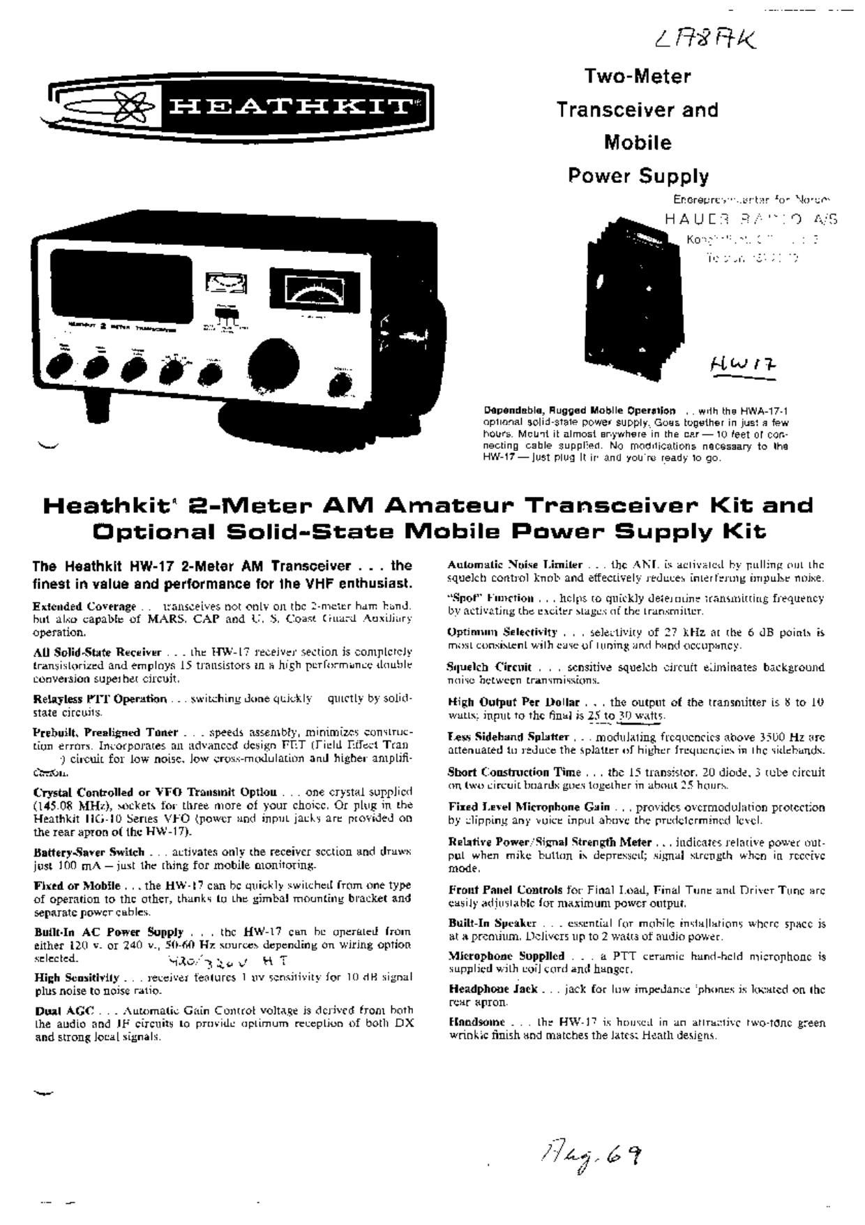
detndnbln, Hugged Iiloblle Operation . , will the HWA-17-l
optlnnal solid-state power supply. Goes together in just a few
hours. Mcu'tl it almost anywhere in the car- to test or corn
nesting cable supplied, No modifications necessary to the
Hw-t7-Just plug It ir and you n: ready to go

Heathkit E-Meter AM Amateur- Transceiver Kit: and
Optional Solid-State Mobile iner Supply Kit:

The Heathklt Hw-t7 2-Meter AM Transceiver . . . the
lines! in value and pertormanca tor the VHF enthusiast.

Extended Coverage . . transcelves not onlv on the 24mm hum i'imd
but alxu capabi: of MARS. CAP and LI. 5. Coast (inurd Auxiliary
operation.

All Soliitsute Receiver . . . lht: HW-la' receiver section is completely
transixlorized and employs 15 transistors in t: high ptrrtir'mimuc iliiuhlr
conveision superhet circuit.

Retains: lll Operufion . . . xwttghing done quickly qulrtly by SOIILL
state circuits.

Prsbuilt. Pruligned Toner . . . speeds assembly, minimum cunning»
[inn ermrx Incorporates an advanced design FET [l'iulil ratio-:1 Tran

~) c'ncuit for low norsc. low amt-mudulannn and higher amplifi-
Gavin

Crystal Controlled or VFO Transmit Option , . one crystal supplictl
(145.08 MHz), sockets for three. more of your choiccl 0r plug in the
Heathkit (i-ID Series VFO (powtr Mnd inn"!- iarkt an: provided on
the tear apron ot the HW-t '1).

BatterySaver Switch . . l autivates only the receiver section and druwx
just 100 mA - just the thing for mobile monitoring.

Find or Mobile . . . the HW-I" can be quickly xwitchcil from one type
of operation to tin: other, thank-.- to Lhr. gimbal mounting bracket and
separate power cables,

Built-In AC Power Supply . . . thc HW-tl can be upcrulell [mm
either 120 v. or 240 v., 50-60 Hz suurw» depending on wiring option
lecctcd. .1351]? 3.9 v' H T

High Scusitlvlly . . . receiver t'ealurcs l nv sensitivity for 10 (iii signal
plus noise to noise ratio.

Dual AGC . . .\uu1ma(ic Gain Control voltage is derived from bath
the audio and JF circuits to prmidu uptimum mchliun of both DX
and strong local signalx

Aulomalic Nuise Limikr . . . tho ANI is activated by pulling out the

Spot hint-non . l . helps to quickly determine transmitting frequency
by activating Lb: |:\Ci.tfr \lugux (if the trummilnzr

Optimum Selectivity . . . selcrtivlty of 2? ).Hz at the 6 dB youth is
must Lnnsiswnl wilh came of tuning and hand ocutpancy

Siluelch Circuit . . . scnsrtive squelch circutt eliminates background
ntti'i'c hclwccn Lramrniuxiuns.

nigh Output Per Dollar . . , the output at the transmitter is S to ll)
walls. Input to the final )5 25 to 30 watts.
..-~ ..__.

fess Sidehand Splatter . . . modulating frequencies above BSUO Hz arc
allenualtd 1n itduce the splatter of highur lruqucnciux 1 Ihc \itichunds.

Short Construction Time . . . the 15 transistor. 20 diode. 3 tum: rircuit
an lwu circuit btianlx gncx lagclhur In about 25 hulirx,

Find Lu-el Mirror-hone Gain . . . provides ovcrmodulation protection
by dipping any voice inpul abuvc ting~ rIrLichCrmincd lc\Ci,

Relative Power-WWII Vrengfih Meter . . . indicates relative power out-
pul when mike button is deflf!\§cli; signal strength when in rccciic
mode.

Front Panel Controls for Final Load, Final Tun: anti Driver Tunc an:
casilt' adjusmblc lot maximum power output.

Builtvln Speaker . . . stunlidl fur mnch inkifllihllflfw whrrc space is
at a premium. DCilVCIS up to 2 watts of audio power.

Microphone Supplied . . a PTT tardmic hand-held microphone is
Vupplicd with uni] snnl anil hangar.

Headphone Jack . . Jack for Inw impedantz phunex is ltxmtcd on the
mar apron
Handsome . . lit: HWJT ix hmltcll lrl un atlrhstix two-tone green

wnnL.c finish and matches the lates; l-luatlt designs.

27/7, é a

Page 2

HW-|7 SPECIFICATIONS

-_,
TRANSMITTER: Benllilvily: 1 microvolt or loss for 10 dB signal-plus-noise to noise
Frequency Coverage: 143.2 MHz lo 148.2 MHz. ratio (30% modulation at 400 Hz).
pom, Input: 251° 30 watts. IF Selectivity: 27 kHz at 6 65 down.
0mm" Imp-dime: 5°42 ohm unbalanced. Intermediate Frequencies: 24.965 MHz and 2 MHz.
Ant-rm: lnpul Impedance: 50-72 ohm unbalanced.
Power Output: 8 to 10 watts.
Audio °u1pul Mir: 1 watt atlassthan10% distortion.
Tranunltung Mode: As emission (AM). 2 watts maximum.
: - . - II | - . 100% l'nntktols: (2) U0734 RF amplifier and mixer: [1) 3155023 HF oscil-
Mcgullgglson Capability Modulation is automation y Inn-ted 0 later: (4) 2N3694 IF amplifiers com. mm. second oscillator:
' [4) 2N3393 audio preamplifier. microphone amplifier. microphone
squelch amplifier; [1) X29A829 Squalch gate; (2) 40050 audio out-
Froqulney Control: Limited to lour Internal crystals or an external PL": 1) 2N1274 audlo driver.
VFO. such as the Healhkit Model HG-lOB.
GENERAL:
cmrar Holder: One Hcsru type and three FTZ43 Iypes. 9 °""I°= Everr 10° H1.
._/
: 4- .
CW9! Muifiptienlionz 18 times. Temperature flange 20 degree C to 50 degree 6
. _ Power Requirements: 120 or 240 volts AC input. 50-60 Hz.
Microphone: Ceramrc PIT (furnished). .
Ballery Saver: 8 watts.
Tubes: 7059 -oacillalor and trlpler; tripler. 12GN7- doubler-driver.
3158 _ PA llnal. Receiver Trans: 20 watts.
Fin-I Tuning: Series tuned, link coupled. SIM: 35 watts.
Note: This. transceiver is wired to power me Heathkil Model HG-IO rrnnsmll: 100 watts.
series VFO.
Cabinet Dimensions: 14%" W. x 6%" D, 1 Elk H. includlng micro-
RECEIVER: phone and feet.
Frequency Courage: 143.2 MHzto 143.2 MHz.
Net Weight: 13 lbs.
Recelvlng Mode: Typo A3 emission (AMJ.
Inpnl Vol-3|: 12 to 15 volts DO. Duty Cycle: 50%.
lnpul Cum-n: 10 ampere: maximum. Convenlon Frequency: 2500 Hz [approxJ
Allow-bl. hmbl-nl I'ornpcrliure: 10 degrees F to 122 degrees F. Dimensions: 3% " W, x 7 5116" L. x 2% " H.
High Volume Output: 380 VDC, no load: 340 VDO at 150 mA load. Nat Weight:3 lbs.
RIpph:Less than 1% 51150 mA. Not..- A 13.5 volt Dc input was used in determining the electrical
specificaliuns.
GmbH
60798prendlingen bei Frankfurt -

Robert-Bosch-Stra Be Nr. 3 2 - 38
Tel. 06103- 6 89 71, 6 8972.6 8973