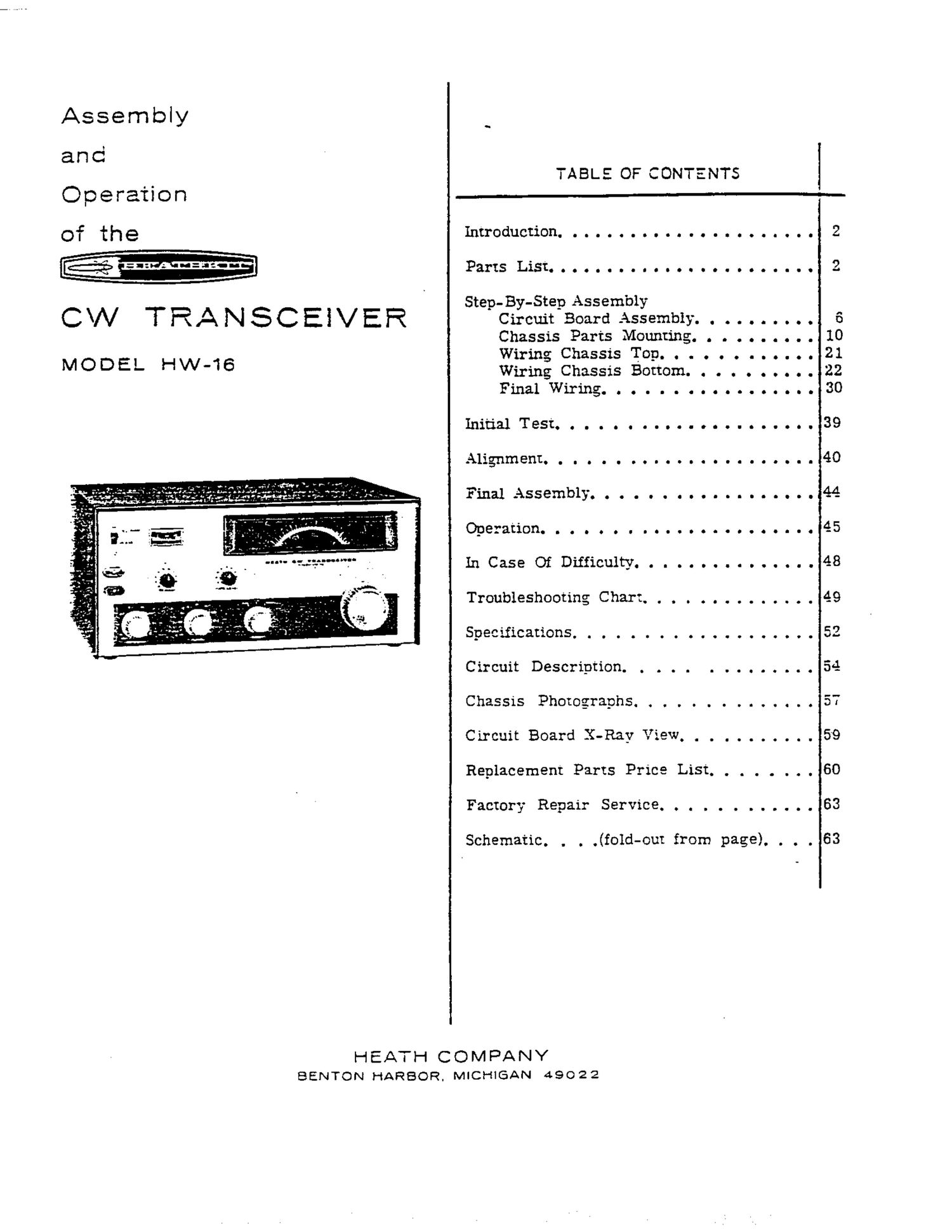
Heathkit HW 16 Manual

This is the 38 pages manual for Heathkit HW 16 Manual.
Read or download the pdf for free. If you want to contribute, please mail your pdfs to info@audioservicemanuals.com.

Page: 1 / 38
left right
Heathkit HW 16 Manual

Extracted text from Heathkit HW 16 Manual (Ocr-read)


Page 1

Assembly

and

Operation

TABLE OF CONTENTS

Introduction. 0 O O O O O . . . . . . . O O I O O C
PartsListQQQOQQQOIOOOCCOI0......

Step- By-Step Assembly

C\N TRANSCEIVER Circuit Board Assembly. .

MODEL

HW-16

Chassis Parts Mounting. . . . . . . . . .
Wiring Chassis T013. . . . . . . . . .. .
Wiring Chassis Bottom. . . . . . . . . .
Final Wiring. C O O I O C O O O O O 0 0 O I 0
Initial Test. 0 O O O O O O O O I O O O I C O O O O .
.Alignment. . g g o o o o I c 0 u c o o o o o o c I I
Final cassemb1).o o o o 0 o a o o I o n t a o o O 0
Operation. I o 0 0 O I I 0 I O O 0 C C O O O O I O C
III case Of Difficulty. O I O O D O l C D O O O I 0

Troubleshooting Chart. . . . . . ........

Spec ificationso a o o C t o o 0 ....... O 9 .

Circuit Description. . . . . . . . . . . . . .
Chassis Phomgraphs. . . . . . . . . . . . . .
Circuit Board X-Ray View. . . . .......
Replacement Parts Price List. ,,,,,, .
Factory Repair Service. . . . . . . . . . . .

Schematic. . . .(fold-out from page). . . .

HEATH COMDANY
BENTON HARBOR. MICHIGAN 49022

[\J

10
21
22
30
39

40

60

63
63

Page 2

Fag mumm-
INTRODUCTION

The Heathkit Model HW-16 CW Transceiver is cryStal controlled for excellent stability, For
a high performance and economical amateur high selectivity, the receiver uses a 500 Hz
radio receiver and transmitter. Although it is crystal filter, The receiver is automatically
designed with the Novice Class operatorinmind, muted each time the key is depressed. providing
this Transceiver is also an excellent piece of full break-in operation. No emernal antenna
equipment for the General Class operator. The relay is required, as antenna switching is
Transceiver provides full break-in CW com- accomplished within the Transceiver.

munications in the lower 250 kHz segments of

the 30-, 40,, and lS-meter bands. The following equipment will be necessary for

the initial test and alignment of the Transceiver.
The transmitter is crystal-controlled, using 1. An 11 megohm input VTVM (a 20 KQ/V
80-meter crystals on 80- or 40-meter bands, VOM may also be used).
and 40-meter cryscals on 40- or Iii-meter bands.
The Transceiver also has provisions for an ex-
ternal VFO.

2. A 50 $2 nonreactive dummy load that is
capable of 100 watts dissipation, such as
the Heathlcit Cantenna, Model HN-Sl.

Input power to the final stage is adjustable for 50 3_ Crystals:

to 90 watts input. A 75 watt marker on the meter. 7.030 MHz or slightly higher frequencv,
which indicates plate current, represents maxi- 3500 kHz or slightly higher frequency.
mum power for Novice Class Operation. All three 3750 kliz or slightly lower frequency.

stages of the transmitter are grid-block keyed.
The only tuning required when changing hands or
frequency is adjusting the final Tune capacitor.

NOTE: Refer to the "Kit Builders Guide" for
complete information on unpacl-zing, parts iden-
tification, tools, wiring, solderi g, and step-
by-step assembly procedures.


The receiver. uses dual conversion for excellent
image rejection and the receiver's front end is


PARTS LIST

NOTE: The numbers in parentheses inthe Parts To order replacement parts, refer to the
List are keyed to the numbers on the Parts Replacement Parts Price LiSt and use the
Pictorial (fold-out from Page '3) to aid in parts Parts Order Form furnished with this kit.
identification.

PART PARTS DESCRIPTION PART PARTS DESCRIPTION
No. Per Kit No. P_e_t_- Kit _ __
RESISTORS Resistors (1/2 Wart] (cont'd.}
1-121 1 120 K52 (brown-red-yellow)
1/3 Wm 1-29 2 220 K52 (red-red-yellow)

(1) 1-41 3 10 $2 (brown-black-black) 1-99 2 240 K52 (red-yellow-yellow)
1-54 1 15 5'2 (brown-green-black) 1-31 1 330 K51 (orange-orange-
1-66 2 150 Q (brown-greembrown) yellow) '

1-42 1 270 Q (red-violet-brown) 1-33 1 4.70 K9 (yellow-violet-

1-6 1 470 Q (yellow-violet-brown) yellow)

1-9 4 1000 5'3 (brown-black-red) 1-35 2 1 megohm (brown-black-
1-13 1 2700 Q (red-violet-red) green)

1-14 4 3300 $2 (orange-orange-red] 1-36 3 1.5 megohm (brown-green-
1-18 2 5600 Q (green-blue-red) green)

1-20 4 10 KS? (brown-black-orange)

1-21 1 15 K9 (brown-green-orange) 1 Watt

1-22 3 22 K0 (red-red-orange) (2}1-2-1 1 1000 El {brown-black-red)
1-25 5 47 K2 (yellow-violet-orange) 1-5-1 1 22 KS) (red-red-orange}
1-60 1 68 K52 (blue-gray-orange) 1-7-1 3 47 KB (yellow-violet-orange)
1-26 5 100 K52 (brown-black-yellow) 1-8-1 1 58 K52 (blue-gray-orange)