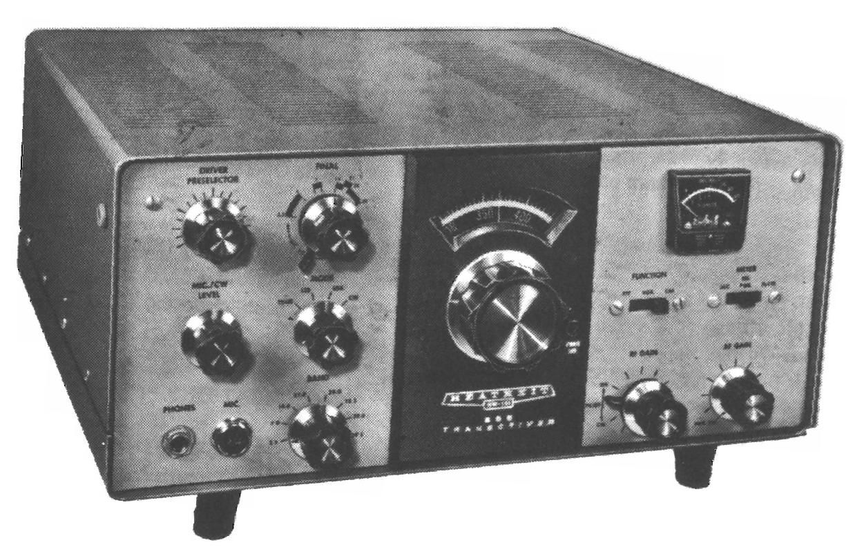
Heathkit HW 101 Manual

This is the 245 pages manual for Heathkit HW 101 Manual.
Read or download the pdf for free. If you want to contribute, please mail your pdfs to info@audioservicemanuals.com.

Page: 1 / 245
left right
Heathkit HW 101 Manual

Extracted text from Heathkit HW 101 Manual (Ocr-read)


Page 1

.M W,

3
.3
.i
i?
:3
,
(
«
i
i

Page 2

HEATHKIT
MANUAL

for the

$83 TRANSCEWER


Model HW-101

595-1 277-1 8

HEATH COMPANY - BENTON HARBOR, MICHIGAN

Page 47

Pagan

l l

l l

( )

\
;e .. 1/4"suEET menu.
sceew @

Detail 74F

Refer to Detail 7-4F and mount a pilot lamp socket at
FU. Use a #6 x 1/ " sheet metal screw.

Bend the socket mounting bracket to an angle of
approximately 45 degrees.

Check to make wre that one of the sheet metal screws
does not touch lug 3 of terminal strip FF. If necessary,
loosen the terminal strip mounting screw and turn the
terminal strip slightly.

( )

l )

4410 x I/Z"
SELF~YAPPING
SCREWS

/ A?
%\i

Refer to Detail 7-46 and insert seven 4-40 x 1/2"
self-tapping screws in the drive mounting plate
(#205-761). Insert the screws until about one-third of
their length emerges on the back side of the plate.

Remove the seven screws. Four of these screws will be
used later in Chassis Assembly" section. Discard the
other three straws.

Page 49

A9

- 4700

PICTORIAL 7-2 Q5
[La

Page 99

Pa9978 -HRLA'IHKIT'


640 l l/_Z"
SELFYAPPING

scasws\y

VFD DIAL

(SCREENEDSIDE) 3.3:ng Q

PICTORIAL 8-9

Refer to Pictorial 8-9 for the following steps.

END OF SCALE

( l Squeeze out some grease from the silicone grease pod
and apply a small amount to the gears of the VFO
tuning capacitor at the point where they meet. Rotate
the shaft several times to distribute the grease to all
the gear teeth.

( ) Remove the protective backing from the circular dial.
Then mount the dial on the drive mounting plate. Use
the 4-40 x 1/2" self-tapping screws, which were put
aside earlier, and the 5/16" long spacers.

( i Turn the VFO shaft to its full counterclockwise
position. Then slip the circular dial with one hand
until the "500" end of the scale is at the 12 o'clock

position as shown in Detail B-QA.

( ) Mount the VFO assembly at area BV with one spade
bolt in each of the four slots. Use #6 lockwashers and

6-32 nuts. The nuts will be tightened later. Be sure the
edge of the circular dial is positioned in the circular
notch at 82. Detail 8~9A

Page 150

MICROPHONE CONNECTIONS

A high-impedance microphone equipped with a push-to-talk
Mitch should be used with the Transceiver so either the PTI'
or VOX methods may be used to turn on the Transmitter. A
two-pin microphone connector (Amphenol 80MC2MI is
furnished for this purpose. It should be connected to the
microphone cable as directed in the following steps.

Heath Microphones

l I Determine the desired length of your microphone
cable, and cut off any excess.

l I Perform the numbered steps in Figure 1-7.

Other Microphones

If you use a microphone different than the one shown,
connect the lead from the microphone element to pin 1 of
the connector. If the microphone has a PTT switch, connect
this lead to pin 2. Swield wires. to complete the ground side
of the circuit, should be soldered to the spring as shown in
Figure L7.

HEATHXITO

9.

PTT
SWITCH

AUDIO

I. REMOVE Irl/B"OF OUTER
INSULATION.

2. REMOVE ALL BUT I/4"OF
THE BRAIDED SHIELD.

3. UNBIIAID THE I/e" or SHIELD
AND THIST THE FINE SHIELD
WIRES TO FORM A STRANDED
LEAD.

A. TWIST THE FINE WIRES OF EACH LEAD TOGETHER AND
APPLY A THIN FILMOF SOLDER TO THE END OF EACH

SHIELD

SLIP THE HOUSING Am SPRING ON THE CABLE.
SEW THE BARE END OF THE GROUND LEAD AND THE SHIELD
BACK OVER THE SPRING AND SOLDER.

sm'rcu
LEAD 2

SDLDEII
GROUND LEAD

AUDIO
LEAD

SOLDER
(SNIELDI

PUSH THE AUDIO LEAD THROUGH PIN I Am THE SWITCH

LEAD THROUGH PINZ OF THE CMECTOR use (NOTE
NUMBERS INSIDE OF CONNECTOR BASEI.

smog: BOTH mus on THE sun, mm cur on- THE excsss mas,
W sown
cur or: excess

SLIP THE HOUSING OVER THE CONNECTOR BASE AND FASTEN
WITH A SETSCREW. FASTEN THE SPRING WITH THE OTHER SE'ISCREW.

Figure 1-7

115

Page 174

OPERATION

NOTE: YOU MUST HAVE AN AMATEUR RADIO
OPERATOR AND A STATION LICENSE BEFORE
PLACING THE TRANSMITTER SECTION OF THE
TRANSCEIVER ON THE AIR. INFORMATION ABOUT
LICENSING AND AMATEUR FREQUENCY
ALLOCATIONS IN THE UNITED STATES IS
AVAILABLE FROM PUBLICATIONS OF THE FEDERAL
COMMUNICATIONS COMMISSION OR THE AMERICAN
RADIO RELAY LEAGUE, 225 West Main Street,
Newington, Connecticut 06111.

Operation of the Transceiver has been simplified as much as
possible to permit rapid adjustment by the operator. Once

the initial settings have been made, it should not be
necessary to readjust most of the controls. Reed the
following information carefully. Good operating techniques
will provide good clean signals and long troublefree life of
the Transceiver.

CAUTION: Be sure a 50 to 75 Q nonreactive load is
connected to the ANTENNA jack before operating the
Transceiver. This load can be an antenna, a dummy load, or
a properly adjusted linear amplifier. (See the "Installation"
section of the Manual on Page 131).

READING THE METER

Figure 1-18 illustrates the meter face. The figures 0 to 9
under the left half of the are are read as "3 units," and the
figures above the right half of the art: are read as "decibels
over $9." The v mark is the point to which the cathode
current is adjusted.

The ALC (automatic level control) position of the meter
switch results in "5 Meter" action during reception, and
indicates the relative ALC voltage during transmission. No S
Meter action can be secured with the meter switch in the
REL PWR or PLATE positions.

The REL PWR position causes the meter to read an
uncalibrated amount of rectified output power. This
position is useful for determining the tuning conditions for
maximum output power.

The PLATE position of the switch causes the meter to read
wthode current to the final stages. There are six numbers on
the S Meter (in additon to 0). When reading cathode current,
each number represents 50 milliamperes. Thus:

Milliamperes of
W

Scale
Number

0
50
100
150
200
250
300

READING THE DIAL

The tuning dial is calibrated in divisions from 0 to 500. Each
represents 5 kHz. The dial reading (in kHzl is added to the
Band switch setting (in MHz) to determine the frequency to
which the Transceiver is tuned. For example:

HEATHKITO

Band switch 14. MHz

Dial reading 235 kHz

Frequency 14.235 MHz

139

Page 196

ALL RESISYAICE VALUES ARE IN WMS (K = I). MEG = LONJMO. O>= INFINITVL
RESISTANCES WERE MESURED WWI-1 I HEITH MmEL IMJI V1Vm

POSITION ALL CONTIOLS Aw ROTLIV QUITCNES IN A FULLY COUNTERCLWKWISE
POSITION. VIEWED FROM THE SHAFT END, POSITIONS 0F SLIDE SWITCHES AIE
CALLED WT ON THE VQJ'AGE CNR'Y. WHEN IMPORTANY.

. MEASURE RESISTANCES BETWEEN CHIHIS Am TNE POINT INDICATED.

BE SURE THE POWER PLUG IS DISCONKCTED.

or BAanquCk
U U U '


IF) fl
SHOULD fie? III-IANGE-
FOR OTHER P05|TION$

@

. WITH FUWTION
SWITCH IN CAL
MSI'TION.


MODE AT TUNE

PTT
VOX
CAL

IOOK
200K
I00 K

O
l

FUNCTION AT OFF

W
mu: 200K a
L3! zoom

us! zoax

cw

RESISTANCE CHART

FIGURE 1-22

Page 225

Page 177


H E AT H K 1 '1
OUYPUT SIGNALs
To vsA (cut err)
AVC To FRODUCY
V4 RECYlFlER was czrscron vlzc
V3 MNZ uua
SECOND IF
eAue wrung:
HRS! if
AMPLIVIER
INPUT
SIGNAL
FROM CRVSTAL
FILTER n. l

was

#102

Woo x
.005

to AVC

mucosa Lvos = :

I2 AND A or

can he to METER
watch 5

ro METEI
swurcn I

tc av
THROUGN LUGS
: Anon or
RELAY M2

AVC

Figure 2-23

V10, first receiver mixer V11, and IF amplifiers V3 and V4.
The dc bias for these stages comes from the following two
sources: from the -dc voltage at the arm of the RF Gain
control; and from the AVC voltage. These two voltage
sources are connected to diodes 0101 and 0905, which act
as a diode gate. This diode gate permits either voltage to
control the gain (of V10, V11, etc.) without interacting with
each other.

From the two diodes, the bias voltage is coupled through
resistor R412 to the grids of V10 and V11, and through
resistor R415 to the grids of V3 and V4. Voltage divider
resistors R415 and R416 cause only one half of the total
bias voltage to be coupled to the grids of IF amplifiers V3
and V4.

AVC voltage is obtained by coupling part of the IF signal
through capacitor C112 to AVC diodes V13A and V133.
These diodes producea negative dc voltage at pin 1 of V13A
that is proportional to the signal strength. This negative
voltage is developed across resistors R124 and R117, and
capacitors C110 and C124. Capacitor C124 charges quickly
to the peak voltage so the AVC will respond quickly to keep
large signals from being distorted in V3, V4, V10, and V11.
Capacitor C110 charges more slowly, and causes the AVC
voltage to be proportional to the average signal level of the
received signal. This produces a fast-attack, slow-release
AVC characteristic.

AVC to v:

AVC TO v4

£116

3,: M
an:
m

10M

mam
SIGNAL
rnoM v4

in]:

.02

VISA
vs aeNa
V133

v3 eeNe
AVC

(no 9
mr =
our
2300
= 3 AVC TO
m we mo vn
V-O 999! cu:
m
I .005

Figure 2-24

An incoming signal that produces a negative AVC voltage
that is significamly hidier than the bias voltage from the RF
Gain control causes the gain of V10, V11, V3, and V4 to be
reduced. This keeps the output of the RF and IF amplifier
stages at a nearly constant level despite wide amplitude
changes in the received signal.

Page 226

Page 178

PRODUCT DETECTOR (Figure 2-25)

The 3.395 MHz signal from IF amplifier V4 is coupled to
the grid of product detector tube V13C. At the same time,

' the signal from carrier oscillator V16 is fed to the cathode of
V13C (3.3936 MHz for the lower sideband, or 3.3964 MHz
for the upper sideband and CW).

These two signals are then mixed together in V130, resulting
in an audio output signal which is the difference frequency
between these two signals. Capacitors (2119 and C121. and
resistor R119 are connected in a filter network that bypasses
any RF signal coming from V13C to ground. but permits the
audio signal to pass through to audio amplifier V14A.

AUDIO AND POWER AMPLIFIER (Figure 2-26)

The signal from the product detector is applied to the AF
Gain control to determine the amount of signal that will be
coupled through capacitor C308 to the grid of audio
amplifier V14A. The audio signal is amplified in V14A and
then coupled to power amplifier V14B. Tube V14B
amplifies the signal further and supplies the audio power

TO ANTI-YRW

cincurr

no:

INPUT SIGNAL
mom Ir AMPLIrIia v4

av


12,2/

(/20 107W

:2

, EH9
oureu1¢-,

SIGNAL m 02 m9 4 6'21 I x353
AUDIO ' V "- vacuum
AMVLIFVER I500: \ autumn
VIAA : 1 \

INPUT
SlC-NAL more
CARRIER osCILLAroH
via

Figure 2-25
through output transformer T301 to the output connectors.
Capacitor 0912 couples a portion of the output back to the
cathode of V14B as negative feedback for less distortion.

Two outputs are provided by the secondary of transformer
T301: a headphone output and an 8 :2 speaker output.
Audio power to the 8 S2 speaker jack is rated at 2 watts
maximum,

An audio signal is also supplied to the anti-trip network
from the plate of V143. In the CW mode, a sidetone signal is
supplied to the network from the plate of V153.

V14A

v: «we

AUDlO
at AMPLIFIER

V143

ll? BGWQ FJE/
AUDlO INPUT

r I a
some AMPL F t 36
raom

PRODUCr
pzrzcmn

ro ru: MUHNG

rncu
Nuwonx AND was

W5!

Figure 2-26