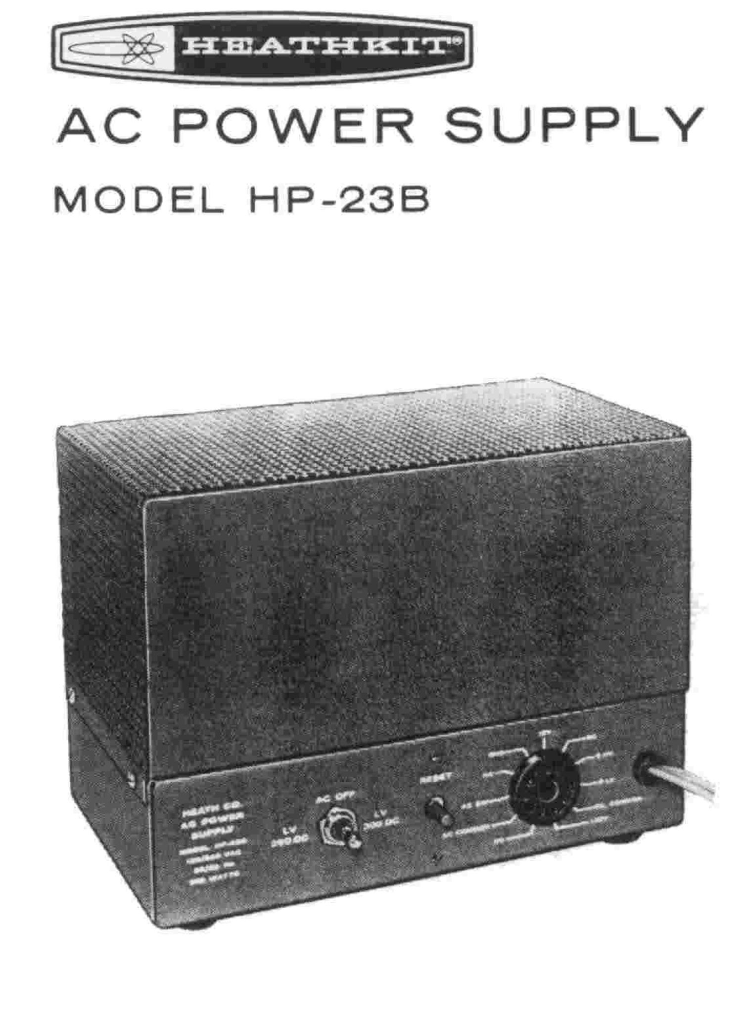
Heathkit HP 23B User Manual

This is the 10 pages manual for Heathkit HP 23B User Manual.
Read or download the pdf for free. If you want to contribute, please mail your pdfs to info@audioservicemanuals.com.

Page: 1 / 10
left right
Heathkit HP 23B User Manual

Extracted text from Heathkit HP 23B User Manual (Ocr-read)


Page 1

AC POWER> SUPPLY

MODEL PIP-238

Page 2

Page 2

INTRODUCTION

The Heathkit Model HP-238 AC Power Supply is designed
to provide all the necessary Operating voltages for fixed
station operation of Heathkit amateur radio transceivers.
The versatility and many features of this Power Supply also
make it ideal for use with many other types of amateur
radio equipment.

The Power Supply features a high voltage source, a choice of
two low voltage sources, a fixed bias source, and a 12.6 volt
filament source. Extensive filtering and good regulation is
provided for the dc sources. The power transformer has a
dual primary winding which can be connected for operation
from either 120 or 240 Vac power lines.

A series connection is provided at the power output socket
to permit turning the Power Supply on or off remotely from

the equipment with which it is used. A toggle switch on the
Power Supply is used to select the value of low 8+ voltage
available at the output socket. The switch also will turn off
the Power Supply. A circuit breaker in the primary circuit
provides overload and short circuit protection.

All output voltage connections from the Power Supply are
made through the power output socket on the chassis. This
provides an easy means of rapidly changing the equipment
from mobile to fixed station Operation.

Read the Kit Builders Guide for complete information on
unpacking, parts identification, too/s, wiring, soldering, and
step-b y-s rep assembly procedures.

CIRCUIT DESCRIPTION

To better understand the circuit operation, refer to the
Schematic Diagram while you read the
description. Each section of the Power Supply will be
discussed individually.

PRIMARY CIRCUIT

The AC OFF switch, circuit breaker, transformer primary,
and two terminals of the power output socket are wired in
series across the ac line. The Power Supply may be
controlled by its AC OFF switch, or by the off-on switch in
the equipment being used with it. The dual primary winding
may be connected in series for 240 Vac line operation, or in
parallel for use on a 120 Vac line.

HIGH VOLTAGE SECONDARY CIRCUIT

The high voltage winding applies approximately 282 volts ac
(rmsl to a full-wave voltage doubler rectifying circuit
consisting of silicon diodes D1, D2, DB, and D4, and
capacitors C1 and C2. These diodes are connected so that
during onahalf cycle, capacitor C2 becomes charged; during
the next half cycle capacitor C1 is charged. Resistors R1,
R2, R3, and R4 are connected in the circuit to provide a
discharge path for capacitors Cl and C2. The capacitors are
charged individually, but discharge in series to produce a dc
voltage equal to approximately twice the applied peak ac
voltage. Excellent dynamic regulation is provided by the

following

large capacitance values of Cl and CZ. The output of the
voltage doubler circuit has a low ripple content and no
further filtering is required.

LOW VOLTAGE CIRCUIT

The low voltage winding is tapped so that either 95 or 125
volts ac (rms) may be applied to a half~wave voltagedoubler
rectifying circuit consisting of diodes DS and DB, and
capacitors C3 and C4. Capacitor C4 is also used with choke
L1 and capacitor CS in a pi filter; C4 is the input capacitor
in the filter network. The use of a high-capacitance input pi
filter network provides a well filtered dc output that has a
very low percentage of ripple.

BIAS VOLTAGE CIRCUlT

The bias voltage is obtained from the low tap on the low
voltage winding. About 95 volts ac (rms) is applied to
half-wave rectifier diode DY. Capacitors CB and C7, with
resistor R7, provide a filter network to remove the ripple
from the bias voltage. -l30 volts of fixed bias is coupled to
the power output socket.

FILAMENT VOLTAGE CIRCUIT

The 12.6 volt filament winding provides 12.6 Vac to the
power output socket.