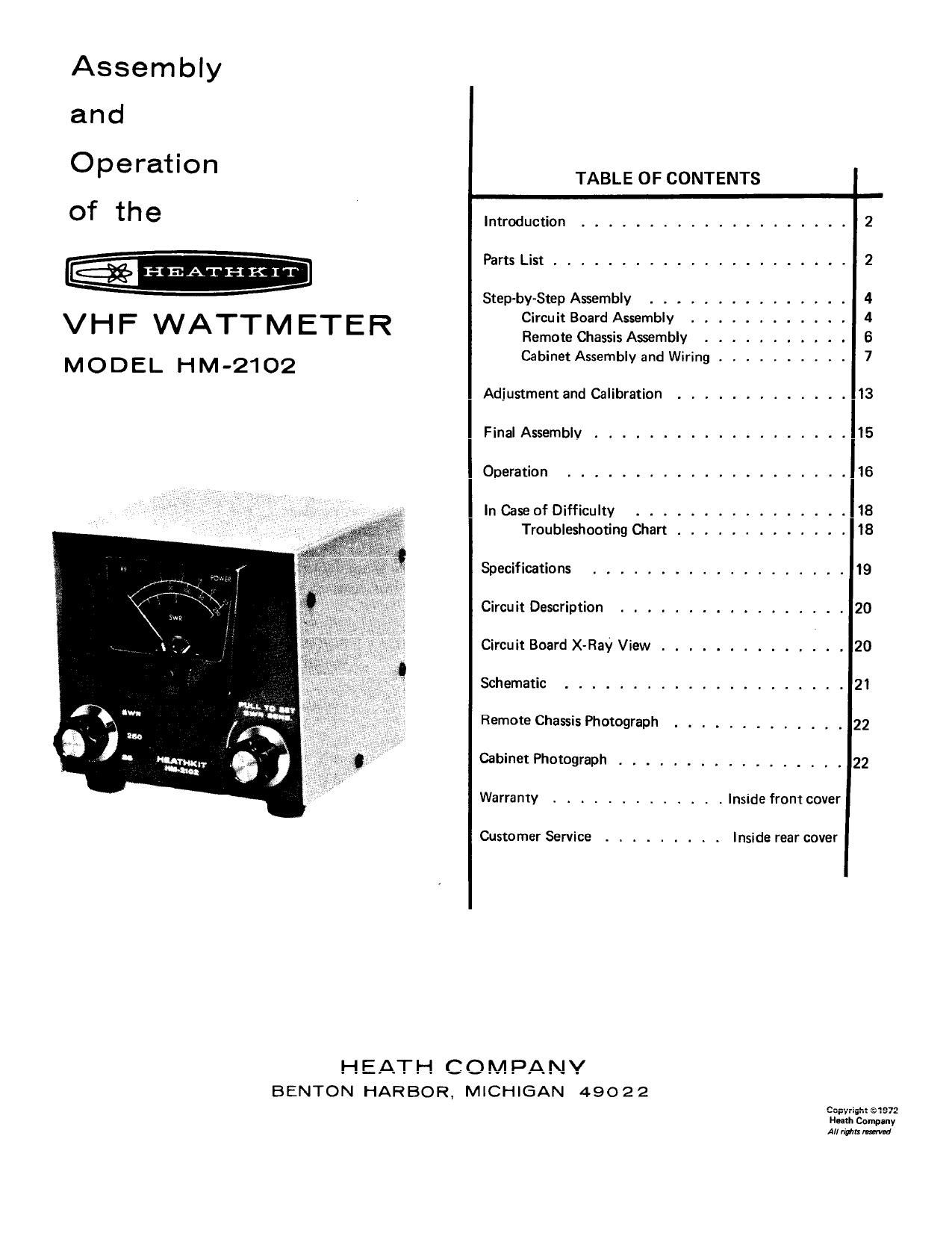
Heathkit HM 2102 Manual 2

This is the 26 pages manual for Heathkit HM 2102 Manual 2.
Read or download the pdf for free. If you want to contribute, please mail your pdfs to info@audioservicemanuals.com.

Page: 1 / 26
left right
Heathkit HM 2102 Manual 2

Extracted text from Heathkit HM 2102 Manual 2 (Ocr-read)


Page 1

Assembly

a n. cl
0 r '
pe atlon TABLE OF CONTENTS
Of th 6 Introduction .................... 2
Parts List .................. . . . . 2
H E AT H K I T
Step-by-Step Assembly ............... 4
\II II- \AIA-F-F-AF-r-r-F- C tBoardAssembly ............ 4
V n '- VV A I I M E I E K Remote Chassis Assembly .......... . 6
Cab'net A mbl nd W' ' .......... 7
MODEL HM-2102 ' Va '9
Adjustment and Calibration ............. 13
Final Assembly ................... 15
Operation ..................... 16
In Case of Difficulty ................ 18
Troubleshooting Chart ............. 18
Specifications ................... 19
Circuit Description ................. 20
Circuit Board XvRaY View .............. 20
Schematic ..................... 21
Remote Chassis Photograph ............. 22
Cabinet Photograph ................. 22
Warranty ............. inSIde from cover
Customer Service ......... Inside rear cover

HEATH COMPANY
BENTON HARBOR, MICHIGAN 49022

Copyridit ©1972
Hum Company
All rims m

Page 2

Page 2

aa

INTRODUCTION

The Heathkit Model HM-2102 VHF Wattmeter is a reliable
instrument for measuring the fonlvard and reflected RF
power of a radio transmitting system in the 50 to 160 MHz
VHF range,

When the Function switch is set to the 25 watt or the 250
watt position, the maximum forward power indicated on the
meter helps you to tune your transmitter for maximum
-ll:_y:_.__,. mu... 4.. _...:.e47I_ E. __A _A .L- nuln _-AA:..A .eL-
Ulllblcllhy. VVIIEII LII: )Wlllall I) )El CI. HIV OVVI" Dclllllg, llll:
Wattmeter measures the reflected power and indicates on
the SWR scale the mismatch between the transmission line
and the load (antenna). This information is also valuable for

anAnnn «AIIIann-lr n» On Anne-"dun H... rnnnnnn: mm- A:
uuwnuu uu'ululn-llu w my \un-n-lnlun- un- "\uquvnvy lulmh VI

the antenna. The circuitry includes an internal calibration
facility for 2-meter and 6-meter bands.

This Wattmeter may be permanently installed in your
transmission line and needs no other power source, The unit
gives negligible insertion loss, however, it is designed only
for a transmission line of a 50 D. nominal characteristic
impedance. The small cabinet is designed for use at your
operating position but for convenience the detector

portion may be re. mounted nearby.

Read Me Kit Builders Guide" for complete information on
unpacking, parts identification, tools, wiring, soldering and

anslhefnn numb/y prawn».

-.-,. ..., -...,. ............ --.._....-.,.

PARTS LIST

Check each part against the following list. The key numbers
correspond to the numbers in the Parts Pictorial (fold-out
from Page 3). To order replacement pans: Use the Parts
Order Form furnished with this kit. If one is not available,
refer to "Replacement Parts" inside the rear cover of the

Manual.

KEY PART PARTS DESCRIPTION PRICE KEY PART PARTS DESCRIPTION PRICE
No, No. Per Kit Each No. No. Per Kit Each
RESISTORS Other

- 1 $2 1- tt -b - 20
1/2-Watt A2 1431 1 Zack} wa (green rown
A1 1-157 2 233?)(yeilow-wolet- .15 A3 250 1 10 k9 precision 1.00
A1 1-44 1 22009 (red-red-red) .15 A? If}??? I E9.k9.°°""°l. . . . . 199
A1 1_105 1 10 k9 (brown-black- .15 Ab 19-155 1 zuu ku control wutn swucn le

orange) (appearance may vary)

A1 1-50 1 68 kQIblue-gray- .15

orange)

Page 25

m Page 2
.M , , _ , ,,
WWI
r"""""'""""""'"""""'""'""'""'l
_DDIKITEF\ (IDIIIII QAAD. II
.. . w my... WW... V,
r-------- ---------u FégTfiJF
: m OUTPUT
. - fl 0
I
I _IE is
l 7.7
| ,5BPF __
I Cl -
I 2,7 To 20
I
: CZ DI C! CO [22:00
: 27 21 ,0
l
R:

NOTES:

1.

IZFF FOR ZMETER
PF FOR 6 METER

CALIBRATION
CALIBRATION


CALIBRATE
JUMPER

C9 CAL

. 005

$3
FU NCTION
SWITCH
(HEAR wzw)

W;

- H - ; _--- 51
L2 L3
FB FB
A A
a

63K

wr-
flu

Cl5

:Ems

CALIBRATE

i 5.
cm 03 W

o
N

N ca
4 V 130 > I30 5
470 470

_J£Il _ng2
.0

$0. 3


r-I PH
5 --------
52
sansmvnv
#3 PSWITCH 3

SENSITIVITY
CONTROL

SCHEMATIC or THE
HEATHKIT®

MODEL HM-2102

ALL RESISTORS ARE 1/? WATT 5% UNLESS OTHERWISE NOTED. 5
RESISTOR VALUES ARE IN OHMS (K-IOOOI

ALL CAPACITORS LESS THAN 1 ARE IN pF; GREATER THAN 1

ARE IN pFI

FUNCTION SWITCH SHOWN IN 25 POSITION

SENSITIVITY SWITCH SHOWN PUSHED INC

VHF WATTMETER

. VTHIS SYMBOL INDICATES CIRCUIT BOARD COMMON

ETHIS SYMBOL INDICATES CHASSIS GROUND,

,iTHIS SYMBOL INDICATES A FERRITE BEADI