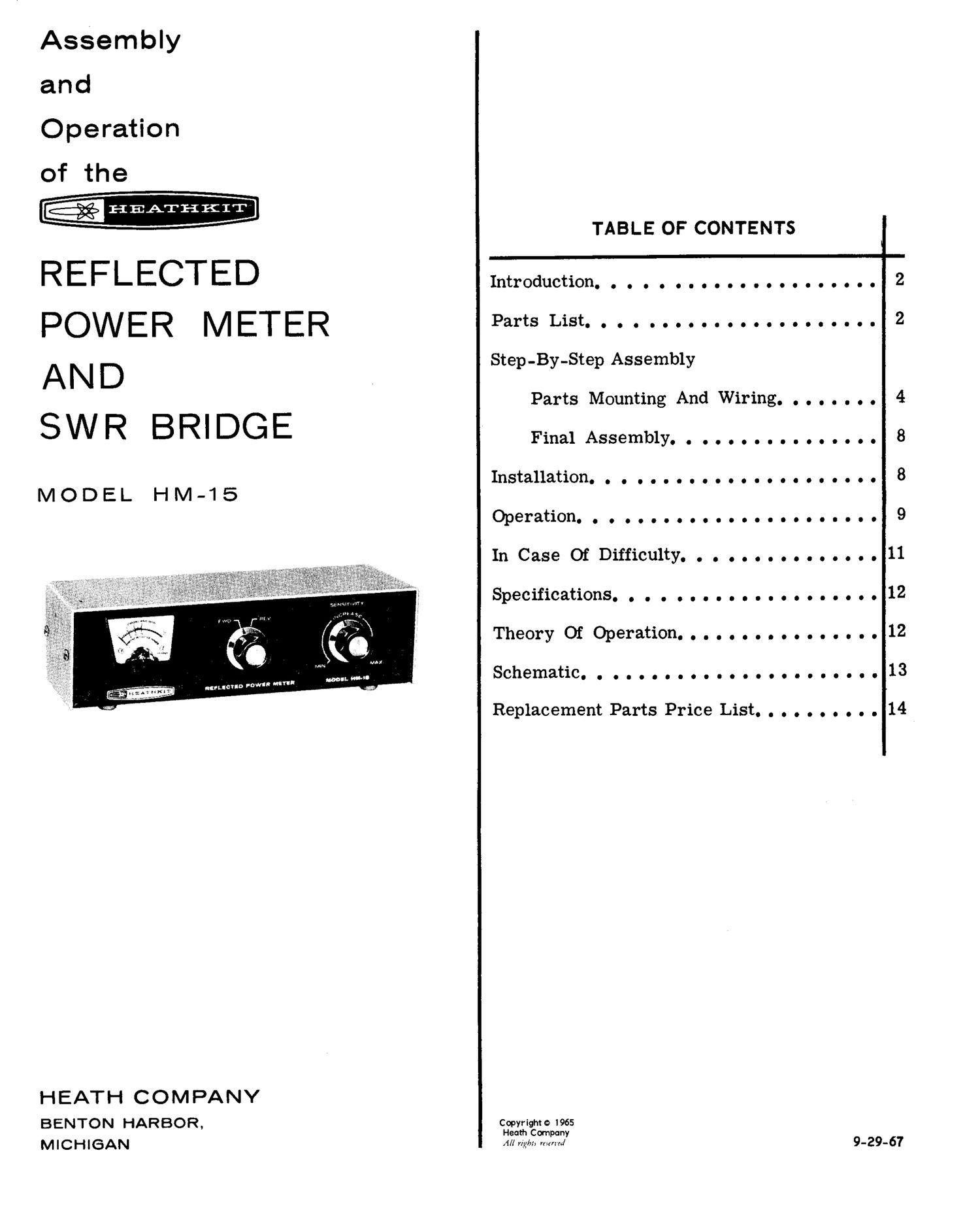
Heathkit HM 15 Manual

This is the 14 pages manual for Heathkit HM 15 Manual.
Read or download the pdf for free. If you want to contribute, please mail your pdfs to info@audioservicemanuals.com.

Page: 1 / 14
left right
Heathkit HM 15 Manual

Extracted text from Heathkit HM 15 Manual (Ocr-read)


Page 1

Assembly
and

Operation
of the

HEATHKIT

TABLE OF CONTENTS

REFLECTED Introduction. . . . . .........
POWER METER PartsList...................... 2

AN D Step-By-Step Assembly

SWR BRIDGE

Parts Mounting And Wiring. . . . . . . . 4
FinalAssembl-yoo00000000000000 8

Installation...................... 8
MODEL HM-15

Operation-co00.000000000000000... 9

In CaseOfDifficulty...............11
SpecificationS....................12
Theory0fOperation................ 12

SChema-tico00000000900000.0000... 13

I unset) POW"

Replacement Parts Price List. . . . . . . . . . 14

HEATH COMPANY
BENTON HARBOR, Copyrightol965

Heath Cornpany

M I C H 1 SAN Alf rig/9r; men'ed 9-29.. 67

Page 2

33:58 2 . - HEATHKIT'

INTRODUCTION

The Heathkit Model HM-15 Reflected Power
Meter and SWR Bridge indicates, reliably but
ineXpensively, whether the RF power output of
your transmitter is being transferred efficiently
to the radiating antenna. The Reflected Power
Meter is primarily intended for use with Ama-
teur Radio transmitters, but it can be used with
other transmitters. If it is used with a trans-
ceiver it will not affect receiver operation.

The combination of very low insertion loss and
high power rating permits the Reflected Power
Meter to be inserted permanently in a 50-52 (2
or 70-75 52 transmission line. This permits con-
tinuous monitoring of reflected power or SWR
(standing wave ratio) to determine proper trans-

mitter tuning, transmission line-to-antenna im-
pedance matching, and relative power output.

The Reflected Power Meter can also be used
for other applications, such as designing antenna
coupling networks, checking other transmission
systems, etc. Because of its small size and the
fact that it needs no external power source, it
can be moved about conveniently. The input and
output connectors are standard VHF coaxial
connectors.

NOTE: Refer to the "Kit Builders Guide" for com-
plete information on unpacking, parts identifi-
cation, tools, wiring, soldering, and step-by-
step assembly procedures.


PARTS LIST

The numbers in parentheses are keyed to the
numbers on the Parts Pictorial to aid in Parts
identification. The instructions in the Kit Build-
ers Guide show you how to identify resistors and

capacitors.
PART PARTS DESCRIPTION PART PARTS DESCRIPTION
No. Per Kit No. Per Kit
RESISTORS HARDWARE .
(6) 250-8 SJ #6 sheet metal screw

1 /2 Watt / (7) 250-172 2/ 3-48 x 3/8" screw
(1) 1-103 1 , 33 $2 (orange-orange-black) (8) 250-49 4"; 3-48 x 1/4 screw

1-83 1? 56 n (green-blue-black) (9) 250-93 2/ 8-32 x 1/4" setscrew

1-146 1/ '75 $2 (violet-green-black) (10) 252-1 6/ 3-48 nut

1-123 1 100 $2 (brown-black-brown) (11) 252-7 21! Control nut

(12) 253-1 2/ . #6 fiber washer

CA PACITORSa-CONTROL-SWITCH-DIODE (13) 253-10 2 / Control flat washer
(2) 21-14 2f r .001 ufd diSC capacitor (14) 254-4 1/ Control lockwasher-
(3) 10-11 1 f 50 K9 control (15) 254-7 8/ #3 lockwasher
(4) 63-177 1 2-position rotary switch (16) 259-10 1v . Control solder lug /
(5) 56-26 21 1N191 diode (brown-

white -brown)