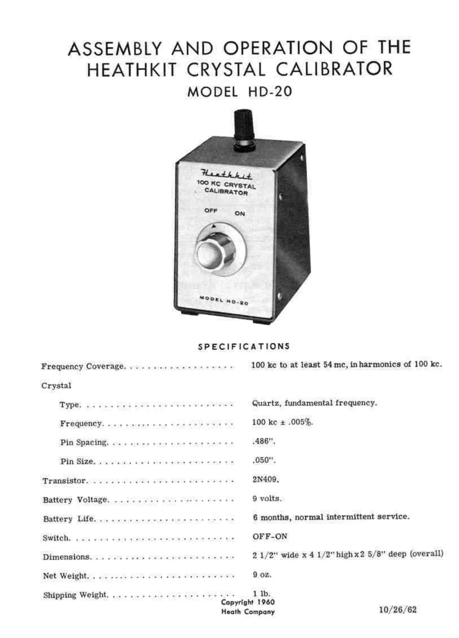
Heathkit HD 20 Schematic

This is the 14 pages manual for Heathkit HD 20 Schematic.
Read or download the pdf for free. If you want to contribute, please mail your pdfs to info@audioservicemanuals.com.

Page: 1 / 14
left right
Heathkit HD 20 Schematic

Extracted text from Heathkit HD 20 Schematic (Ocr-read)


Page 1

ASSEMBLY AND OPERATION OF THE
HEATHKIT CRYSTAL CALIBRATOR
MODEL HD-20

noon. ML")

SPECIFICATIONS

Frequency Coverage ................... 100 kc to at least 54 me, mharmonics 01 100 kc.
Crystal

Type. ....... . ................. Quartz. fundamental frequency.

Frequency. . . . . .................. 100 kc i .005%.

Pin Spacing ...................... .486".

Pin Size ........................ .050".
Transistor. ........................ 2N409.
Battery Voltage. ..................... 9 volts.
Battery Life ........................ 6 months. normal intermittent service.
Sulitch. ........................... OFF-ON
Dimensions ......................... 2 1/2" wide x 4 1/2" highx2 5/8" deep (overall)
Net Weight .......................... 9 oz.
Shipping Wetght ...................... 1 1b.

Copyright I960
Heclh Company 10/26/62

Page 2

INTRODUCTION

The HEATHKIT" Model BID-20 Crystal Cali-
brator Is an accmte 31918.1 source which pro-
vides output signals a: 100 kc intervals up to
54 msgacycles. Amfleur Radio Operators can
use the HID-201w manypurposes suchu check-

ing receiver dial calibration, checking band
limits, receiver RF alignment, etc.

The I-ID-ZO will also find use in other phases 0!
radio communications which require accurste
marker signals at multiples of 100 kc.

SCHEMATIC DIAGRAM

.0035 um
I f
I \
UHF
o H comm-r
I I
(W KC =
CRY5'IAL .
.-o
g can
A .-
IO 8- 5° -
F IF": .ha -
uu uuF 9V _
BATTERY :_
+
---o
o
N
TRENSI4ggOR
OFF

CRYSTAL CALIBRATOR
MODEI. run-20

Page-2

Page 10

(I i MALE
3%??an ' BATTERY
con Ton
CONNECTOR EC

Pictorial 3

Refer to Pictorial 3 for the following steps.

( ) Connect the wire coming through the grom- { ) Connect one end of a 3" hookup wire to lug
met {ram the transistOr socket to lug 2 01 1 of the switch (5-1).
the switch and the control solder lug (8-1).
The wire Should he 50158113 t30 b0? 1113 2 t ) Install the female (+J battery connector on
and the solder lug. the other endof this bare wire (5-1). Crimp

the connection before solder-in ,
( ) Install the male (-) battery connector 0n the 3

end of the remaining wire coming through
the grammet (8-1). Crimp this connection
before soldering.

Page 10