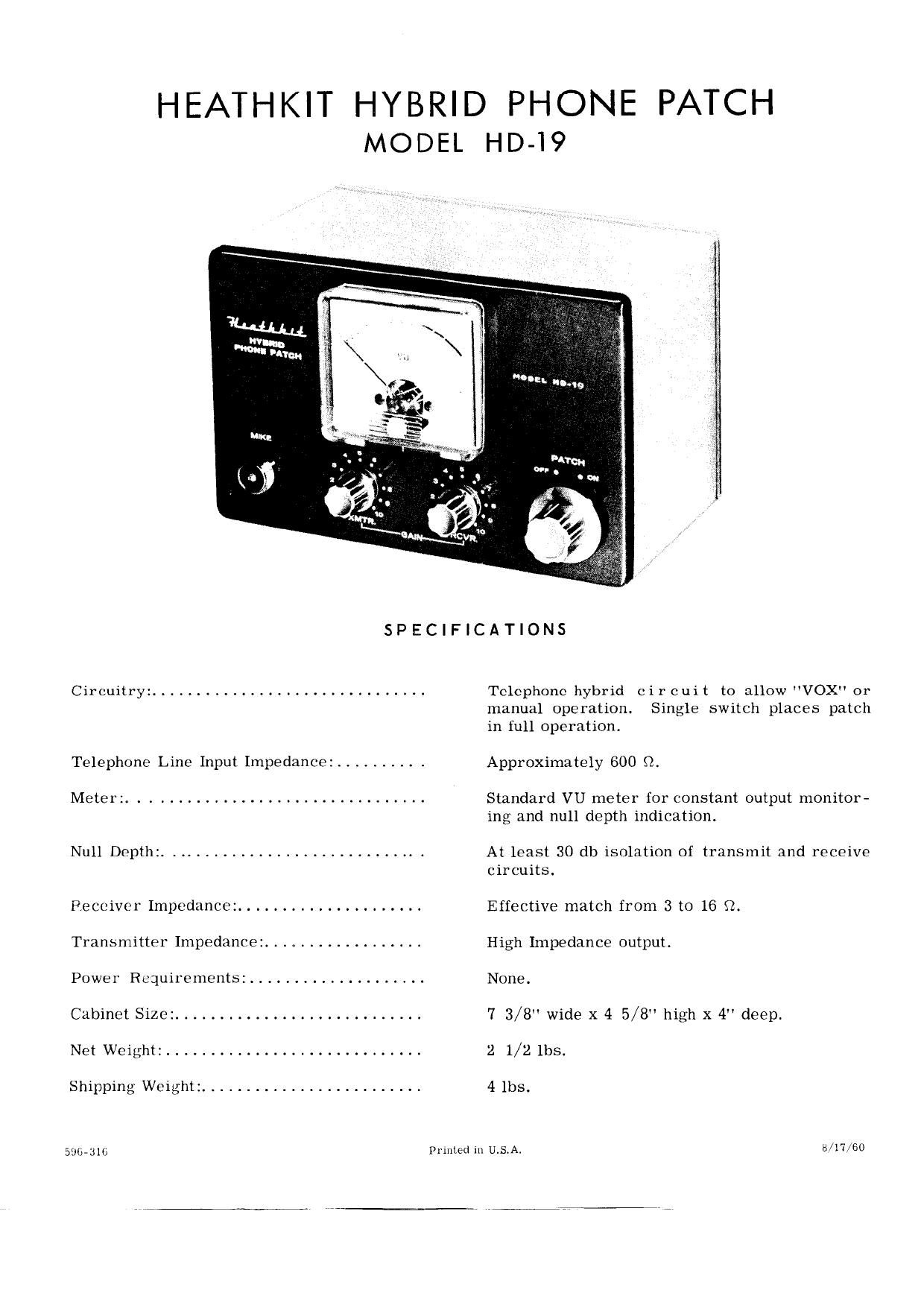
Heathkit HD 19 Schematic Manual

This is the 4 pages manual for Heathkit HD 19 Schematic Manual.
Read or download the pdf for free. If you want to contribute, please mail your pdfs to info@audioservicemanuals.com.

Page: 1 / 4
left right
Heathkit HD 19 Schematic Manual

Extracted text from Heathkit HD 19 Schematic Manual (Ocr-read)


Page 1

HEATHKIT HYBRID PHONE PATCH
MODEL HD-I9

SPECIFICATIONS

Circuitry: ...............................

Telephone Line Input Impedance: ......... .

Meter: .................................

Null Depth: ............................. .

Receiver Impedance: .....................
Transmitter Impedance: ..................
Power Requirements: ....................
Cabinet Size: ............................
Net Weight: .............................

Shipping Weight: .........................

Sslbdilb

Telephone hybrid cir cuit to allow "VOX" or
manual operation. Single switch places patch
in full operation.

Approximately 600 Q.

Standard VU meter for constant output monitor-
ing and null depth indication.

At least 30 db isolation of transmit and receive
circuits.

Effective match from 3 to 16 f2.
High Impedance output.

None.

7 3/8" wide x 4 5/8 high x 4" deep.
2 1/2 lbs.

4 lbs.

Printed In UiS.A. {3/17/60

Page 2

INTRODUCTION

The HEATHKIT Hybrid Phone Patch, Model
HD-lQ, is designed to accomplish the transfer
of audio signals between telephone lines and
two-way radio communication equipment with
maximum performance plus ease of installation
and operation. It can be used with nearly all
transmitters and receivers onthe market today,
including transmitters employing "VOX" voice
control operation.

The HD-19 employs a standard VU meter for
accurate monitoring of the output to the telephone
line to prevent crosstalk, and a single function
ON-OFF switch accomplishes all switching for
ease of operation.

The panel controls consist of a function switch
(PATCH OFF-ON), transmitter gain (XMTR),
receiver gain (RCVR) and a microphone con-

nector (MIKE). The null-monitor switch (MON.
NULL), microphone output (MIKE OUT.), and
null adjust control (NULL ADJUST) are located
on the rear chassis apron, as are the receiver
and telephone connections. The null-monitor
switch allows the VU meter to be used as a
sensitive indicator of proper null adjustment.

With the null control properly adjusted, a mini-
mum of 30 db isolation exists between the re-
ceiver output and transmitter input circuits of
the patch, resulting in stable VOX operation.
In addition, the leads to the telephone line are
well filteredfor RF but still maintain a high de-
gree of audio fidelity.

In order to minimize hum, the speciallydesigned
hybrid transformer incorporates additional wind-
ings to present a balanced load to the telephone
line.

CIRCUIT DESCRIPTION

The circuit of the HEATHKIT Model HD-19 is
based on the use of a special hybrid transformer.
The hybrid transformer, with proper adjustment
of the balancing network, will provide a high de-
gree of isolation of the receiving circuit from
the transmitting circuit. This feature is re-
quired for stable voice control VOX operation.

The operation of a hybrid transformer can best
be shown by referring to Figures 1 and 2.

Figure 1 shows the patch in the transmit cycle,
that is, energy from the telephone line is being
routed to the transmitter. The turns ratio of the
hybrid transformer is such that the impedance
of windings C, D and Zt are equal. A voltage E

(representing an incoming voltage of the tele-
phone line) impressedon the transformer will
cause, at a given instant, current flow as shown
by the arrows. The opposing voltage drop across
winding C will equalthat across Zt- The identi-
cal winding D is linked by the same flux as
winding C and will, therefore, have an induced
(opposing) voltage of equal magnitude and in the
same direction as winding C. The induced vol-

tage in winding D is equal to the voltage across
Zt, and since their like polarities are connected
together, no currentflow will occur through Zb.
The result is that one-half ofthe incoming energy
is available at the transmitter input and the other
half is dissipated across Zr.

Figure 1
2i T: it
Z1 = Telephone line impedance
51: = Balance network
Z1 A Zb

Windings A = B and C = D
Zr Receiver output impedance
Zt Transmitter input impedance

II II

Page 3