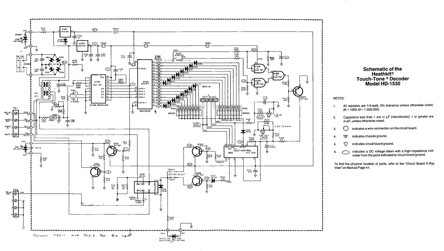
Heathkit HD 1530 Schematic

This is the 5 pages manual for Heathkit HD 1530 Schematic.
Read or download the pdf for free. If you want to contribute, please mail your pdfs to info@audioservicemanuals.com.

Page: 1 / 5
left right
Heathkit HD 1530 Schematic

Extracted text from Heathkit HD 1530 Schematic (Ocr-read)


Page 1

751

REIIfiAY I @ W"
5&9110 2 e. %é>
Augie 3 Q are?" ©
I
MUTE 4 @%©-

-----------------------------------------------------------------------------------------------------------------m-----.
----


' I
I
' i
I rate; I
0 r: I
L.J
' i
I
: :
rmos t'SIOG I
, I: 1-1 I
I - U I
I ERN :
G RESET I
cut JUMPERS
| 270 m, RED l
. 2.00-"--. :
F: mos I
l f 1 mos
-ISTR05£ I
I "9'99 *m I
I
9 I
I nice I
I '30 mm I
I v 6) 443-371 I
I Is 56
-56
I 22 DATAA ( I :
I a DATA} I
: 3 DArAz I |
I % DATAI DIGIT SELECT c114 I
I TH IST 3354 933: 417-50: I
I 23 INHlBIT I i. 1 h I
I or M? nacawaa I d ; : r_ _ 1 I
I o goook~ hfi50i#ABCDI
I - . __l _ ______ __IFIO R131 I
DECODER -
t «<2»ng «)ng l
009 9999 9900 99 5mm R132 31025 I
I I I I I I I I AOJUST 2M SEC I
Ri03 r9102 (:10? C193 WRONG DIGIT RESET "29 TIMER R"26 I
| 4 7° '0 2 :- DIGI r 3"" $3,;- I
SELECT b< RED l
OPTION 0% I5 SEC To e um |
YEL Dias I
56-56 I
R127 I
. -
I 9134 ADJUST mes I
6 0103 I
5 417-218 . 3 2 H 31...? . cm I
9m 4m 2ND RESET 470»: I
m 3m) :57 '
Locn CONTROL I
mos 443-1290 I
I R112 I
I mos 100 I
I 100 4 3 9 6 I
I I
I 41 1%?6 I
I E or I
I TOGGLE
cnz __
I 101 FQN">- 0 I I
K PTION SELECT _
I 69-105 0 33 012? V l
I I » l
| TIMED I
TIMED
I cui- I
I I
I
mess
I 9L 56-56 :
I I
I
| Noaw I I
OPEN 1 K I
I NORM/ I
| L , I cats:
I up I
l I
I I
I I
' I
I $253 I
' I
I I
I I
' I
-------------'----_---_------------------ --------n---@ --- -----------uo--------hi.-n------------ufl-----------------ll
_ vror. ram
Comnqc-t 752" 3"; 782-2 30h 8J1. @1qu ._<
DEVICE on was

mm: Aron/25' 412-642

Schematic of the
Heathkit®
Touch-Tone ® Decoder
Model HD-1530

NOTES:

1. All resistors are 1/4-watt. 5% tolerance unless otherwise noted.
(K =1000, M =1.000.000)

2. Capacitors less than t are in uF (microfarads); 1 or greater are
in pF, unless otherwise noted.

indicates a wire connection on the circuit board.
indicates chassis ground.
indicates circuit board ground.

6. O indicates a DC voitage taken with a high-impedance volt-
meter from the point indicated to circuit board ground.

To find the physical location of parts, refer to the Circuit Board X~Ray
View" on Manuai Page 41 .

Page 2

Page 38

Heathkit"

CIRCUIT DESCRIPTION

Before describing the internal circuits of your
Touch-Tone Decoder, we recommend that you read
the following information on DTMF [dual~tone
multi-frequency} signals. Although not a part of the
working components of your unit, it provides an in-
teresting description of the reasons for and usages
of this type of communications signaling.

TOUCH-TONE (DTMF) CODING

More than 25 years ago, the need for an improved
method of telephone dialing was recognized. The
pulse dialing used during this earlier period Was not
only slow. but suffered from severe distortion over
long wire loops - the distance between your tele-
phone and its switching exchange. This distortion
was even more severe on the cross-country distances
between the company exchanges. This method used
a DC voltage path through all of the involved tele-
phone and exchange circuits, from the caller to the
called party.

A new signaling method was developed which used
a pair of intermixed [AC] audio signals within the
human audible range, and proved to be a very reli-
able alternative to the older pulse dialing system.
This new signaling method was called dual-tone
multi-frequency (DTMF) and was registered under
the name Touch-Tone® dialing. As the name im-
plies, a valid DTMF signal is the sum of two tones
of different and specific frequencies. This tone-pair
is comprised of tones taken from two groups; the
low group consisting of four different tones from 697
to 941 Hz and the high group consisting of four dif-
ferent tones from 1209 to 1633 Hz. The matrix
scheme for combining these eight different tones al-
lows 16 different combinations. Ten of these-codes
are the numerals, while the other six are the symbols
* and # and the letters A, B, C, and I). These
last six are used for special functions in most appli-
cations. Note also that some telephone keypads
incorporate only 12 of these symbols, leaving out
the alphabetic keys.

The new tone signal system was not only a break-
through for the telephone, but for other types of com-
munication as well. The signals are fast and accurate
even over great distances, but more importantly,
they lend themselves nicely to remote control in all
types of communication work. Each communica-
tions keypad, like the one on your telephone, is set
up in a matrix pattern in rows and columns as
shown in Figure 4. Note that the alphabetic column
is omitted in the 12-key configuration. Each key,
therefore, selects a single tone from the low group
row and one from the high group column.

For example, when you dial the number 1, the resul-
tant DTMF tones will consist of one from the low
group [697 Hz) and one from the high group [1209
Hz]. Similarly, all subsequent numbers that you dial
will consist of a unique pair of tones.

HIGH GROUP
1209 Hz 1336 Hz 1447 Hz 1633 H2
LOW GROUP
697 Hz 1 2 3 A
770 Hz 4 5 6 B
852 Hz 7 8 9 C
941 Hz * 0 # D

Figure 4

This DTMF coding system ensures that only one

.tone from each low and high group is represented

in the audio signal. All that remains is for a decoding
process at the terminal or receiving end. Note also
that a great advantage in this process is that the
audio signals, just as voice signals, can be impressed
on an RF carrier to be transmitted over indefinite
distances without any need for directly-connected
wire linkages.