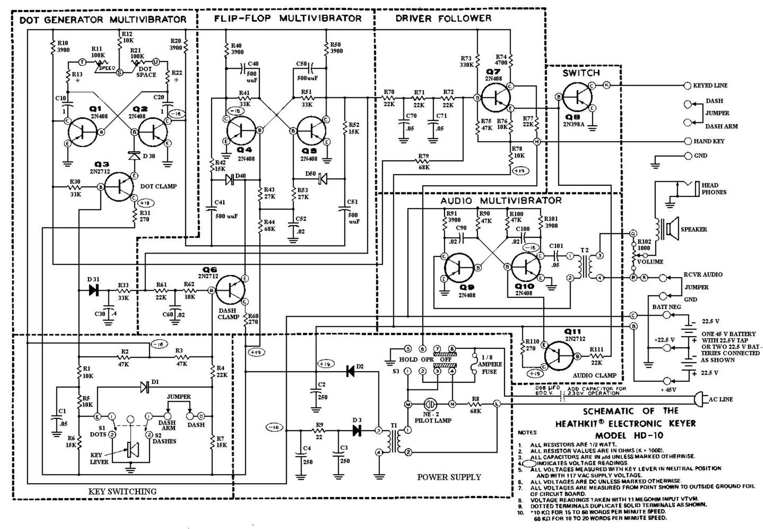
Heathkit HD 10 Schematic 2

This is the 9 pages manual for Heathkit HD 10 Schematic 2.
Read or download the pdf for free. If you want to contribute, please mail your pdfs to info@audioservicemanuals.com.

Page: 1 / 9
left right
Heathkit HD 10 Schematic 2

Extracted text from Heathkit HD 10 Schematic 2 (Ocr-read)


Page 1

'-_-__-__----------------_-_-_-'_----------_-----------_-_ _-___________--_-----------

: DOT GENERATOR MULTIVIBRATOR

1----'-u----n-----------------.-

FLIP-FLOP MULTIVIBRATOR

DRIVER FOLLOWER

RN
3900

L----nun------------------.-

R50
3900

R52
15K
R42 mm mm: =
15K
--1>uM 34
R43 R53
27K ZTK
C41 ' C51
z: = :
sun up 500
R44 _ £5: uul
sax .u:

uwmum

DASH

DASH ARM

.--______-------_--_-J------__--.

AUDIO -MULTIVIBRATOR


D31

c3133:

---------L----------q

C60 .02

---r-n-----_

SPEAKER

22.5 V

p------------I

I

----------------_-----fl------------J--------------------- ----.---'---------------

l
R2 R3
M VW :
31 47K 47K R4 :
10!: I
I
I
10K '
Cl :
'05 D051} _ _ : -|6
- 5
_ RE I
ISKE DASHES é! :
KEY I
m I
KEY SWITCHING i

C
I250

POWER SUPPLY

-n-u-u-n-n-u-u1

r----

WTES

l
2.
1
4
5
6.
2.
a
0.
o

ONE 45 V BATTERY
Wl'l'H 22.5V TAP

OR TWO 22.5 V BAT -
ms CONNECTED
AS SHOWN

AUDIO CLAMP I -5 V


~05! U70 ADD CAPACITOR FOR
600 v. zaov OPERATION

*fiV

q;
SCHEMATIC OF THE

HEATHKITQ ELECTRONIC KEYER

ACLIN'E

MODEL HD -IO

RLL RESISTORS ARE 1 f2 WATT.

ALL RESISTOR VALUES ARE IN OHMS (K ' 1000].

ALL CAPMITORS ARE IN Md UNLESS MhRKED OTHERWISE.
EWICATES VOLTAGE READINGS-

ALL VOLTAGES MEASURED WITH KEV LEVER IN MEUTRRK mlTlON
AND IT" I 17 VAC SUFFLY VOLTAGE

ALL VOLTAG 55 ARE m UNLES MAR [ED DTNE WISE.

ALL VOLTAGE!» ARE MEASURED FROM POINT Sm" TO OUTSIDE GROUND FOIL

OF CIRCUIT WARD.

VOLTAGE READINQ TAKEN WITH 1 "Em! IMPUT WV,

DOTTED TERMINALS DWLICATE SOLID TERMINALS AS SHOWN.

«om FOR 15 To an WORDS ER MIMJTE EEO.

cam FOR 10 TO 2|) WORDS FER MIMJIE SPEED,

Page 8

-HEATHI{IT

Page 39

The collector output of Q5, as shown in Fig-
ure 15, is coupled to the junction of resistors
R33 and R61. Resistor R33, diode D31, capac-
itor C3, resistors R61 and R62, and capac-
itor C60 form filters. These filters direct
voltage from Q5 to clamp Q3 and Q6 to make
the dashes self-completing. They also keep the
control voltage from interacting between dots
and dashes.

The output from the collector of Q5 is also
coupled through a delay line consisting of re-
sistors R70, R71, R72, and capacitors C70 and
C71 to the base of Q7. This delay is necessary
to insure that the output switching caused by
the flip-flop multivibrator slightly overlaps
that of the dot generator, while making dashes.
Failure to overlap may leave holes in the
dashes similar to that caused by the bouncing
contacts of relays.

When the collector output of Q5 remains at its
maximum negative voltage level, it produces a
negative voltage to turn on transistors Q7 which
drives Q8. Betore Q5 can switch to on, the flip-
flop must be triggered again by a positive going
pulse from the collector of Q2. The pulse that
just triggered Q5 wasapositive goingpulse from
Q2. The output from the dot generator multi-
vibrator is now a negative voltage from the col-
lector of Q1. This is fed to the base of Q7, which
is already on because of the negative voltage
at 95, Therefore, the output from Q1 has no
additional effect. The next pulse from Q2 will
be a negative going pulse, as Q2 turns off.
This negative pulse from Q2 has no effect on
the flip-flop multivibrator, as only positive
going pulses can reset it. After the dot gen-
erator multivibrator goes through another half
cycle, a positive going pulse from Q2 will
result. This positive pulse is coupled to the
base of Q4 (saturated transistor), resetting
the flip-flop multivibrator.

Note in Figure 14 that the flat portion of the
waveform is equal to the length of a dot and a
space. This is because Q2 produces apositive
going pulse every time it switches on. Since the
positive pulses switch the flip-flop transistors
alternately, they operate at half the rate of the
dot generator multivibrator. The outputfrom the
dot generator and flip -flop multivibrators add at

//

/DOT SPACE/DOT/SPACE
/ /

Krona REFERENCE ONLY

0 VOLT

- l 3VOL'I'S

70 TI 1': TJ 1'4
TIME
05 COLLECTOR VOLTAGE
Figure 15

the base of Q7. This produces the first third
of a dash signal from the collectors of Q] and
Q5, as shown in Figure 15. The middle third of
the dash is produced by the collector output of
QS alone.

é/pé sucsfi /

/'/

SPACE

bros nusssucc ONLY

0 VOLT
-16 VOLT!
T0 Ti T2 T3 T
TIME
01 COLLECTOR VOLTAGE
Figure 16

The last third of the dash is filled in by the next
dot signal from Q1 alone as shovm in Figure 16.
The result of these two signals at the base of
Q8 is the waveform show in Figure 17,

03%seacego/t cs
an
4-3:; A 6 +144

+1.5 VOLTS
O VOLT!
-0.2 VOLTS
TD Ti T2 T3 T4
TIME

SIGNAL AT BASE OF 08
Figure 17