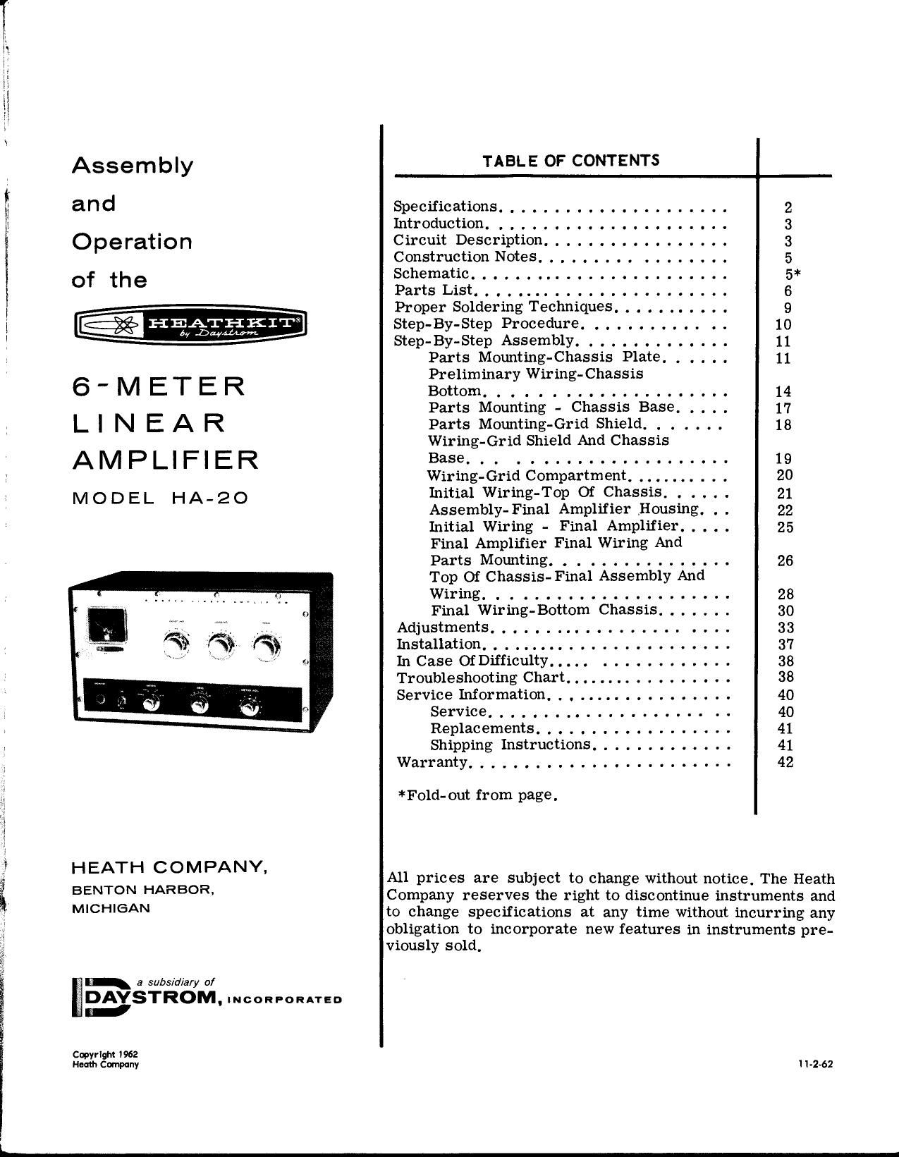
Heathkit HA 20 Schematic Manual

This is the 46 pages manual for Heathkit HA 20 Schematic Manual.
Read or download the pdf for free. If you want to contribute, please mail your pdfs to info@audioservicemanuals.com.

Page: 1 / 46
left right
Heathkit HA 20 Schematic Manual

Extracted text from Heathkit HA 20 Schematic Manual (Ocr-read)


Page 1

I

mmwm.

Assembly
and
Operation
of the

1-]: BATH KIT
,5. .Daywam

6'METER
LIN EAR
AMPLIFIER

MODEL HA-20

HEATH COMPANY,

BENTON HARBOR,
MICHIGAN

a subsidiary of

DAYSTROM. moon-annual:
H

Cwyrlyl! I962
Heath Cmny

TABLE OF CONTENTS
Specifications ..................... 2
Introduction. .................. . . . 3
Circuit Description ................. 3
Construction Notes ....... . . . . . . . . . . 5
Schematic. . . . . . . ................. 5*
Parts List. . . . . ................... 6
Proper Soldering Techniques ........... 9
Step-BY-Step Procedure. ............ 10
Step-By-Step Assembly. ............. 11
Parts Mounting-Chassis Plate. . . , . . 11
Preliminary Wiring- Chassis
Bottom ................... 14
Parts Mounting - Chassis Base. . . . . 17
Parts Mounting-Grid Shield . . . _ , 18
Wiring-Grid Shield And Chassis
Base... . .......... 19
Wiring-Grid Compartment... . . . . . 20
Initial Wiring-Top Of Chassis . . . . . 21
Assembly- Final Amplifier Housing. . . 22
Initial Wiring - Final Amplifier ..... 25
Final Amplifier Final Wiring And
Parts Mounting. . . ............. 26
Top Of Chassis- Final Assembly And
Wiring. .................... 28
Final Wiring- Bottom Chassis ....... 30
Adjustments .......... . ....... . . . . 33
Installation ........................ 37
In Case 0fDiIficu1ty..... ......... . . . 38
Troubleshooting Chart.... . . . . . . . . . 38
ServiceInformation.................. 40
Service ...................... 40
Replacements .................. 41
Shipping Instructions ............. 41
Warranty ............. . .......... 42
*Fold-out from page.

All prices are subject to change without notice. The Heath
Company reserves the right to discontinue instruments and
to change specifications at any time without incurring any
obligation to incorporate new features in instruments pre-
viously sold.

I 1-2-62

Page 2

- imam

Page 2
SPECIFICATIONS
Driving Power Required ................ 2.5 to 10 watts P.E.P.
Power Input ......................... 125 watts P.E.P. SSB.
75 watts DC AM.
Power Output To Antenna. . . . . . ......... 70 watts P.E.P. SSB.
Output Impedance. . . . ................. 50 to 75 $2 nonreactive,
Output Coupling. . . . . . . ...... . ........ Link.
Input Impedance ...................... Approximately 50 9.
Input Coupling. ...................... Link (tuned grid).
Frequency Coverage. . ............... . 49,8 to 54 megacycles.
Panel Metering ............. . ........ 0.6 ma grid current.
' 0-400 ma plate current,
0-1000 volts DC plate voltage.
0-1000 relative power.
Tube Complement. . ..... . . . .......... 2 - 6146 push-pull power amplifiers,
1 - 0A2 voltage regulator.
Power Supply ....................... . Filament: 6.3 volts at 4 amperes,
Spare: 6. 3 volts at 4 amperes.
Bias: Negative 150 volts DC.
Plate Supply: 600 volts DC.
Self-contained blower.
Power Requirements ........... . . . . . . . . 95 watts standby.
200 watts maximum, at 117 volts AC, 50/60 cps.
Cabinet Size ........................ 10-1/8" high x 16-5/8" wide x 10" deep,
Net Weight ................. . ....... 33 lbs.
Shipping Weight ...................... 43 lbs.

Page 22

Page 22

ASSEMBLY-FINAL AMPLIFIER HOUSING amplifier housing (#206-M199)- Use 6-32 x
I 1/4" hardware. Position the offset of each
Refer to Pictorial 9 for the following steps. spade bolt as shown.

( ) Mount eight 6-32 spade bolts on the final

Pictorial 9

( ) C13. Referring to Detail 9A, mount the
variable capacitor (#26-50) and the shaft
support bracket (#204-M514) at location
BG. Use the flat washer and nut supplied
on the capacitor. Be sure to use the small
hole in the bracket for mounting. SMALL HOLE

Detail 9A

Page 27

( )

( )

( )

( )

( )

( )

( )

( )

Refer to Detail 11B and start two 8-32 x
1/8" allen setscrews in an insulated shaft
coupling. Position the shaft coupling on the
shaft of capacitor BC so that it is 3/16" from
the bushing of the capacitor and tighten,

Make a pencil mark 1/4" from one end of
the 3-3/4" insulated shaft extension. Pass
this end of the shaft extension through
bushing BH and into the insulated shaft
coupling on capacitor BC to the pencil mark,
then tighten the setscrew. Center the shaft
in bushing BH and tighten the nuts that hold
the insulated capacitor mounting board and
capacitor mounting bracket to the chassis
plate.

Install the 6146 tubes in sockets V1 and V2.
Bend the neutralizing stubs clear of the
tubes.

Mount the aluminum anode caps to the plate
caps of the 6146 tubes. Use 6-32 x 1/4"
screws. Tighten the screw just enough
to hold the cap in place. Overtightening
will damage the tubes.

L4, RFCl. Locate the anode strips and coil
assembly (#140-27). Mount the anode strip
and one end of the coil assembly on each of
the anode caps of the 6146 tubes. Use 6-32
x 1/4" screws. Donottighten. Bendthe anode
strips so they fit over lugs 1 and 2 of
variable capacitor BC. Be sure to place the
screw in the hole nearest the end on the
anode strips. Position the coil assembly
so the link coupling coil is centered in the
wide space opening of the coil assembly and
tighten the Screws.

R4. Connect a 15 Q (brown-green-black)
2 watt resistor from the top of the anode
strip as near the anode cap as possible of
tube V1 (8-1) to lug 1 of variable capacitor
BC (8-2). Be sure the anode strip is clear
of the capacitor plates.

R5. In a like manner, connect a 15 {Z (brown-
green-black) 2 watt resistor from the top of
the anode strip of tube V2 (5-1) to lug 2 of
variable capacitor BC (S-Z).

RFCI. Connect the free lead ofthe RFchoke
coming from coil assembly L4 to feedthrough
capacitor BM (S-l). Position the choke as
shown.

Page 27
' I/4"
fi-BZX l/B
SETSCREWS 3 w
Detail 11B

NOTE: When rotating the large dial pulley back
and forth, link coupling coil L3 may touch coil

ass

embly L4 where the RF choke is connected.

If this happens, loosen the collar and reposition
it so it stops coil L3 about 1/8" from coil
assembly L4, then retighten the setscrew in the
collar.

Refer to Detail 11C for the following steps.

( )

( )

( )

6- 32Xl/B
I/SETSCREW

/ COLLAR
SHAFT ASSEMBU

CONTROL NUT

CONTR
/ ma

ASHER

PULLEY
SLOTS
/


. /
mo STOP /

v4" HEX.
BUSHING

Detail 11C

Mount a 1/4" hex bushing and 180 degree
rotational stop (#266-18) at location BQ on
the shaft support bracket. Use a control
lockwasher and nut. Position the rotational
stop as shown.

Install the small dial pulley shaft assembly
(#100-M162) in bushing BQ. Use the rollpin.
Position the roll pin and the slots in the
pulley as shown.

Start an 8-32 x 1/8" allen setscrew in a
shaft collar. Position the collar onthe shaft
of the dial pulley shaft assembly at BQ
and tighten temporarily.

Page 33

Page 33

ADJUSTMENTS

PRELIMINARY CHECK
(See Pictorial 14 fold-out from Page 30,)

Set the controls for these checks as follows: LOADING: 0

FINAL: 0
_ POWER: Off. BIAS ADJUST: Full CCW
i METER: Grid CUT OFF BIAS JACK: Open
§ GRID: 0 ,
METER ADJ: 0 Using a 20 KO per volt or higher ohmmeter,
COUPLING - Full counterclockwise make the following checks.

POSITIVE LEAD RESISTANCE
TO POINT

Lug 2 of K Lug 4 of K Infinite.

Chassis ground Lug 1 of B 230 Q.

Chassis ground Lug 5 of B At least 150 Kn after 5 seconds.

S Lug 4 of C Lug 1 of B Approximately 30 KS),

Lug l of B Lug 4 of C Appreciably lower than the previous reading
with the meter on the same range, This reading is
dependent on the voltage impressed across the

; diode and will vary if range setting of meter
1 is changed.

5 Chassis ground Feedthrough AR Approximately 50 K9 after 10 seconds,

Chassis ground - Feedthrough AS Approximately .1 Q (will show zero on most
meters).

Chassis ground Feedthrough AT Approximately 27 K9.

we re, gross; A:

If any of the above readings cannot be obtained,
refer to the In Case Of Difficulty section of the
manual on Page 38.

CAUTION: IN A LINEAR AMPLIFIER, LETHAL NOTE: If at any time while making the adjust-

VOLTAGES ARE PRESENT. CONSEQUENTLY, ments, the Amplifier does not perform as it
; GREAT CARE MUST BE EXERCISE-D WHEN should, refer to the InCase Of Difficulty section,
3 ANY TESTS OR ADJUSTMENTS ARE MADE.

Page 41

Page 41

Under the conditions specified in the Warranty,
replacement parts are supplied without charge;
however, if the Service Center assists you in
locating a defective part (or parts) in your
kit, or installs a replacement part for you,
you may be charged for this service.

HEATHIGT equipment purchased locally and
returned to Heath Company for service must be
accompanied by your copy of the dated sales
receipt from your authorized HEATHKIT deal-
er in order to be eligible for parts replacement
under the terms of the Warranty.

THIS SERVICE POLICY APPLIES ONLY TO
COMPLETED EQUIPMENT CONSTRUCTED IN
ACCORDANCE WITH THE INSTRUCTIONS AS
STATED IN THE MANUAL. Equipment that has
been modified in design will not be accepted
for repair. If there is evidence of acid core
solder or paste fluxes, the equipment will be
returned NOT repaired.

For information regarding modification of
HEATHKIT equipment for special applications,
it is suggested that you refer to any one
or more of the many publications that are avail-
able on all phases of electronics. They can be
obtained at or through your local library, as
well as at most electronic equipment stores.
Although the Heath Company sincerely welcomes
all comments and suggestions, it would be im-
possible to design, test, evaluate and assume
reSponsibility for proposed circuit changes for
special purposes. Therefore, such modifications
must be made at the discretion of the kit builder,
using information available from sources other
than the Heath Company.

REPLACEMENTS

Material supplied with HEATHIGT products
has been carefully selected to meet design re-
quirements and ordinarily will fulfill its function
without difficulty. Occasionally, improper op-
eration can be traced to a faulty component.
Should inspection reveal the necessity for re-
placement, write to the Heath Company and
supply all of the following information.

A. Thoroughly identify the part in question by
using the part number and description found
in the manual Parts List,

B. Identify the type and model number of kit
in which it is used,

C. Mention date of purchase.

D. Describe the nature of defect or reason for
requesting replacement.

The Heath Company will promptly supply the
necessary replacement. PLEASE DO NOT RE-
TURN THE ORIGINAL COMPONENT UNTIL
SPECIFICALLY REQUESTED TO DO S0. Do
not dismantle the component in question as
this will void the guarantee. This replace-
ment policy does not cover the free replace-
ment of parts that may have been broken or
damaged through carelessness on the part of
the kit builder.

SHIPPING INSTRUCTIONS

In the event that your instrument must be re-
turned for service, these instructions should be
carefully followed.

Wrap the equipment in heavy paper, exercising
care to prevent damage. Place the wrapped
equipment in a stout carton of such size that
at least three inches of shredded paper, ex-
celsior, or other resilient packing material
can be placed between all sides of the wrapped
equipment and the carton. Close and seal the
carton with gummed paper tape, or alternately,
tie securely with stout cord, Clearly print the
address on the carton as follows:

To: HEATH COMPANY
Benton Harbor, Michigan

ATTACH A LETTER TO THE OUTSIDE OF THE
CARTON BEARING YOUR NAME, COMPLETE
ADDRESS, DATE OF PURCHASE, ANDABRIEF
DESCRIPTION OF THE DIFFICULTYENCOUN-
TERED. Also, include your name and return
address on the outside of the carton. Preferably
affix one or more "Fragile" or "Handle With
Care" labels to the carton, or otherwise so mark
with a crayon of bright color. Ship by insured
parcel post or prepaid express; note that a
carrier cannot be held responsible for damage in
transit if, in HIS OPINION, the article is in-
adequately packed for shipment.