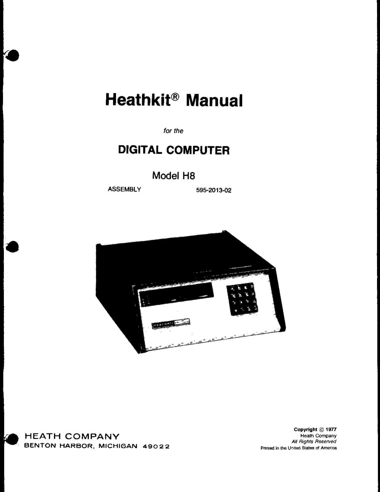
Heathkit H 8 Manual

This is the 65 pages manual for Heathkit H 8 Manual.
Read or download the pdf for free. If you want to contribute, please mail your pdfs to info@audioservicemanuals.com.

Page: 1 / 65
left right
Heathkit H 8 Manual

Extracted text from Heathkit H 8 Manual (Ocr-read)


Page 1

Heathkit® Manual

for the

DIGITAL COMPUTER

Model H8

ASSEMBLY 595-2013-02

Copyrigm © 1977

HEATH COMPANY Heath Company

All Rights Reserved
' BENTON HARBOR. MICHIGAN 4902 2 anad in Ihe Umlea States M America

Page 2

Page 2 '
-HEAIHKITE
TABLE OF CONTENTS
UNPACKING ................................ 3 CONTROL CIRCUIT BOARD
Parts List .................................... 34
Step-by-Step Assembly ...................... 37
ASSEMBLY NOTES .......................... 4 Circuit Board Installation ..................... 55
Circuit Board Checks ......................... 56
CHASE ASSEMBLY CPU CIRCUIT BOARD
Parts List .................................... 7 .
Step-by-Step Assembly 9 Replacement Parts List ....................... 59
"""""""""""" CircuitBoardlnstallation 61
Mother CiTCUit Board Assembly ------------ 9 Circuit Board Check .......................... 61 I
Chassis .................
Power Supply Tests .......................... 30 FINAL ASSEMBLY .......................... 62

Page 9

Ci

Page 9

STEP-BY-STEP ASSEMBLY

MOTHER CIRCUIT BOARD
ASSEMBLY

In the following steps» you will be
given detailed instructions on how to
install and solder the first part on the
circuit board Read and perform each
step carefully. Then use the same
procedure whenever you install parts
on a circuit board.

I
l/sitmu the mother circuit

board as shown in the identifi-
cation drawing with the printed

syefnot the foil side) up,

PART I
NUMBER

IDENTIFICATION
DRAWING

(M12: Hold a 10 kfl [hrown-
black-mange) resistor by the
body as shown and bend the
leads straight down

PUSH DOWN
HERE

[:1 Push theleadsthmugh the holes

at the indicated location on the
circuit board. The end with
color bands may be positioned
either way.

[liress the resistor against the Cir-
cuit hoard, Then bend the leads
outward slightly to hold the re-
sistor in place.

«Liege

PICIORIAL 1.1

[

] Solder the resistor leads in the
circuit board as follows;

1 Push the soldering iron
tlp against both theI lead
and the circuit brim-d hill.
Heat both for two or three
semnds.

sownmu
IRON /

COMPONENT


tiRCUll BOARD

27 Then apply solder to the
other side of the connec-
tiunr llViPORTANT [.ot
the hoalnd lnad and the
circuit huard inil melt the
solder,

SOI DtRING
|RO\


it As the solder begins to
melt allow it to flow
around tin: connection
Then remove the solder
and the iron and let the
connection coolv

SOLDERlNG

[ Cut all the excess lead lengths
close to the connection WARN-
ING: Clip the leads so the ends
will not fly toward your t: -

[ q/Lhenk the Connecticut Compare

ittothe illustrations on Page 10.
After you have checked the sol
der connections proceed with
the assembly on Page 11 Use
the same soldering procedure
for each connection.

Page 33

Page 33

-HEATHKIT'
[ } Set your meter to measure +15 volts DC.
. [ } Touch the meter probe to plug P1 pin 49. The meter should indicate between +9 and +12 volts.
PROBLEM P05333LE CAUSE

1. Low readqng.

Translmmer T3 wiring.
Capacitor CZ.
Switch SW2 or SW3

2. High reading.

Transformer T1 winng.
Switch SW2 or Swa.
Resistor Rt

.05? 0F?

( ) Push the POWER switch to OFF

[ ] Unplug the line cord.

[ ] Disconnect the meter leads from the mother circuit board.

[ ] Remove the pieces of insultion from plug P1 pins 1 and 48.

This completes the Power Supply Tests." Proceed to Control Circuit Board"

Page 52

Page 52

w

20-
6-112"
4.. 3..
l/4"-- r. 2 1H_'
1/4 .-
BRNX j,» BRN
- [-l/4" P-1/4" DH: :3: RED
. ORG
ORG I Ll . GHQ YEl
1/4"
GRN 1/4 l- v-1»3IA
END A 1.3/4u_..
END 3
BLU
VIOL
mscmo/ V

l Detail 3-130

('J ) Refer to Detail 3-130 and separate a 20" length
of B-wire cable into a 5-wire cable and a 3-wire
cable as shown. Discard the 3-wire cable; it will
not he used.

[l ] Prepare the 5-wire cable as shown in Detail
3-13C.

Install a spring connector [#432-866) on each
wire at end B of the cable

( l

( ] Locate the 5-hole connector shell.

N TE: Disregard any numbers stamped into the
5- ole connector shell when you perform the follow-
in steps.

[ Locate the keyboard label set and cut out the
1-5" label. Remove the label from its protec-
tive backing and press the label onto the 5-hole
connector shell as shown in Detail 3-130.

Refer to Detail 3-13D and insert the spring con~
nectar on the brown wire into hole 5 of the
5-hule connector shell.

TOP CONNECTOR
SHELL

Insert the spring connectors on the remainder of the
'res into the connector shells as follows:

( ) Red wire into hole 4 of the 5-hole connector
(

shell.

Yellow wire into hole 2 of the 5-hole connector
shell.

[

w

Green wire into hole 5 of the TOP connector
shell,

shell.
& Orange wire into hole 3 of the 5-hole connector
[ J

Prepare a 4 length of small black wire.

[I
[ Install a spring connector [#432-866] on one
end of the prepared wire.

A
g

Insert the spring connector on the end of the
black wire into hole 1 of the 5-hole connector
shell.

BACONNECTOR
SHELL

15 LABEL

SLOTS
Z;

on 7

Detail 3-13D

.. . n. .l..;.