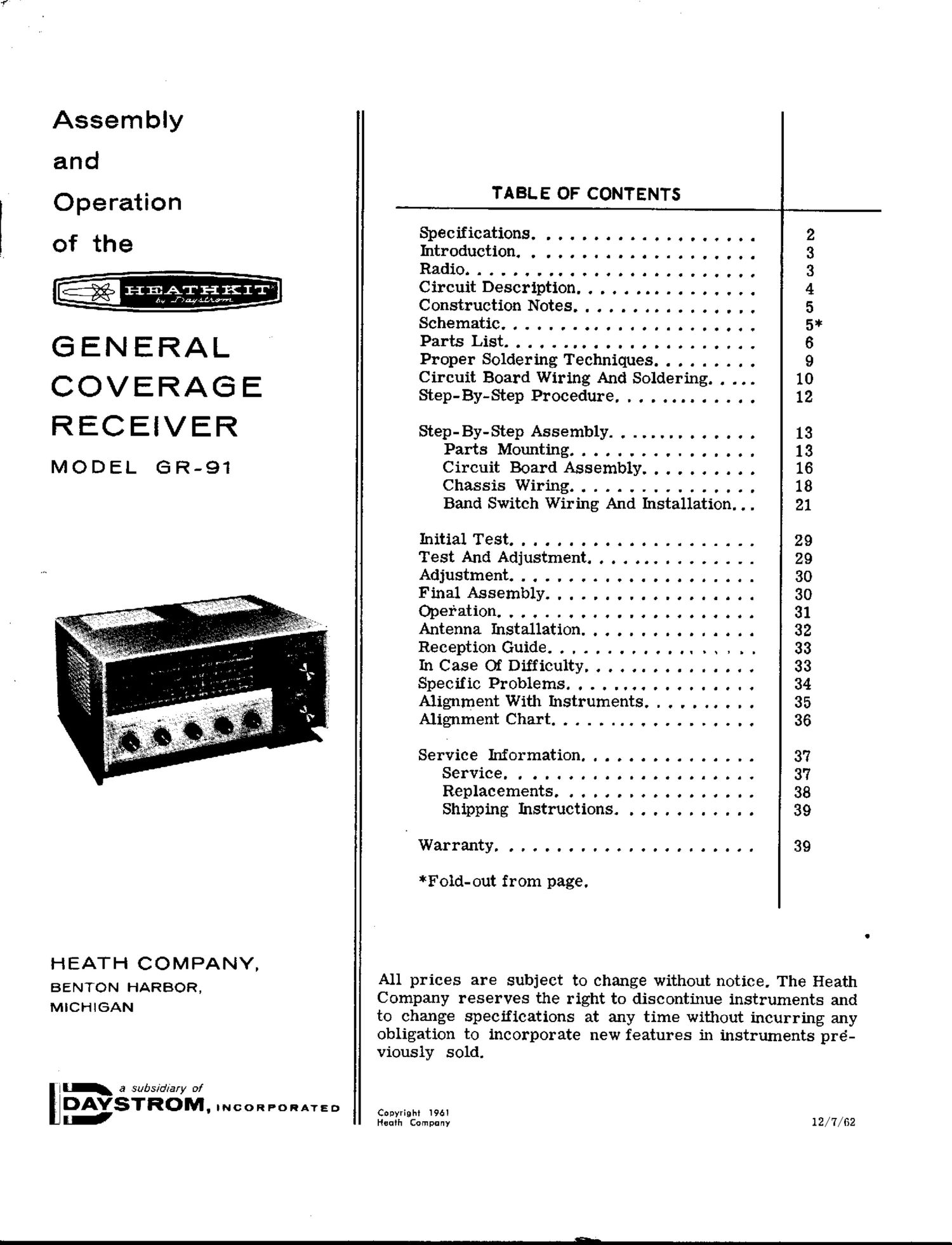
Heathkit GR 91 Schematic Manual

This is the 45 pages manual for Heathkit GR 91 Schematic Manual.
Read or download the pdf for free. If you want to contribute, please mail your pdfs to info@audioservicemanuals.com.

Page: 1 / 45
left right
Heathkit GR 91 Schematic Manual

Extracted text from Heathkit GR 91 Schematic Manual (Ocr-read)


Page 1

Assembly

and

Operation
of the

GENERAL
COVERAGE
RECEIVER

MODEL (SR-91

HEATH COMPANY,

BENTON HARBOR.
MICHiGAN

It a subsfdfary Of
DAVSTROM. mCORPORATED
ad

TABL E OF CONTENTS

Specifications. ......... . . ..... 2
Introduction. . ........ . ......... 3
Radio ......................... 3
Circuit Description ................ 4
Construction Notes ............ . . . . 5
Schematic ................... . . . 5*
Parts List. . . . .................. 6
Proper Soldering Techniques ......... 9
Circuit Board Wiring And Soldering. . . . . 10
Step-By-Step Procedure. . . . . . . . . . . . . 12
Step-By-Step Assembly. . . . . . . . . . . . . . 13
Parts Mounting ................ 13
Circuit Board Assembly .......... 16
Chassis Wiring ................ 18
Band Switch Wiring And Installation. . . 21
Initial Test ..................... 29
Test And Adjustment ............... 29
Adjustment ..................... 30
Final Assembly .................. 30
Operation ...................... 31
Antenna Installation ............... 32
Reception Guide .................. 33
In Case Of Difficulty ............... 33
Specific Problems. . ............... 34
Alignment With Instruments .......... 35
Alignment Chart .................. 36
Service Information ............... 3'?
Service. . ................... 37
Replacements. ................ 38
Shipping Instructions. ........... 39
Warranty. ..................... 39

*Foid- out from page.

All prices are subject to change without notice. The Heath
Company reserves the right to discontinue instruments and
to change specifications at any time without incurring any
obligation to incorporate new features in instruments pre-
viously sold.

Copyright 1961
Heath Company 12/7/52

Page 2

SPECIFICATIONS

Frequency Range -

BandAW... .......
BandB......... ....... .. ......
Band C . ........... . . . .
Band D .................. . ......
S Meter . . . . . ............ .
Headphone Jack. . . . ............... . . .
Controls And Switches. . . . .. ......... . . .
Tube Complement. . ..... . ...... . . . . . .
PowerSupply....... ..............
Power Requirements. . . ............. . .
DimenSiOIlS. . a a a a a ooooooooooooooooo
Net Weight ........ .. .........

Shipping Weight. . . . ............ . .

55D kc to 1600 kc.

1.8 me to 4 me.

4 me to 10 mo.

10 me to 30 me.

Indicates relative signal strength.

For most commercial headphones (headphone
resistance may be from 50 $2 to 10 K9).

VOLUME control with power ON-OFF switch.
BFO control with ON-OFF switch.

Selector Switch with AM, STBY, and CW posi-
tions.

BAND switch.

ANT TRIM.

BAND SPREAD TUNING.

MAIN TUNING.

ANL (Noise Limiter) ON- OFF switch.

IZBEB oscillator and mixer.
12BA6 IF amplifier and BFO.
12AV6 detector and audio amplifier.

- 50C5 audio output.

Silicon diode used as a half-wave rectifier in
conjimction with a power transformer.

105-125 volts, 50/60 cps AC, 30 watts.

12-1/4" wide x 5-1/4" high x 8-1/4" deep.
9 lbs.

15 lbs.