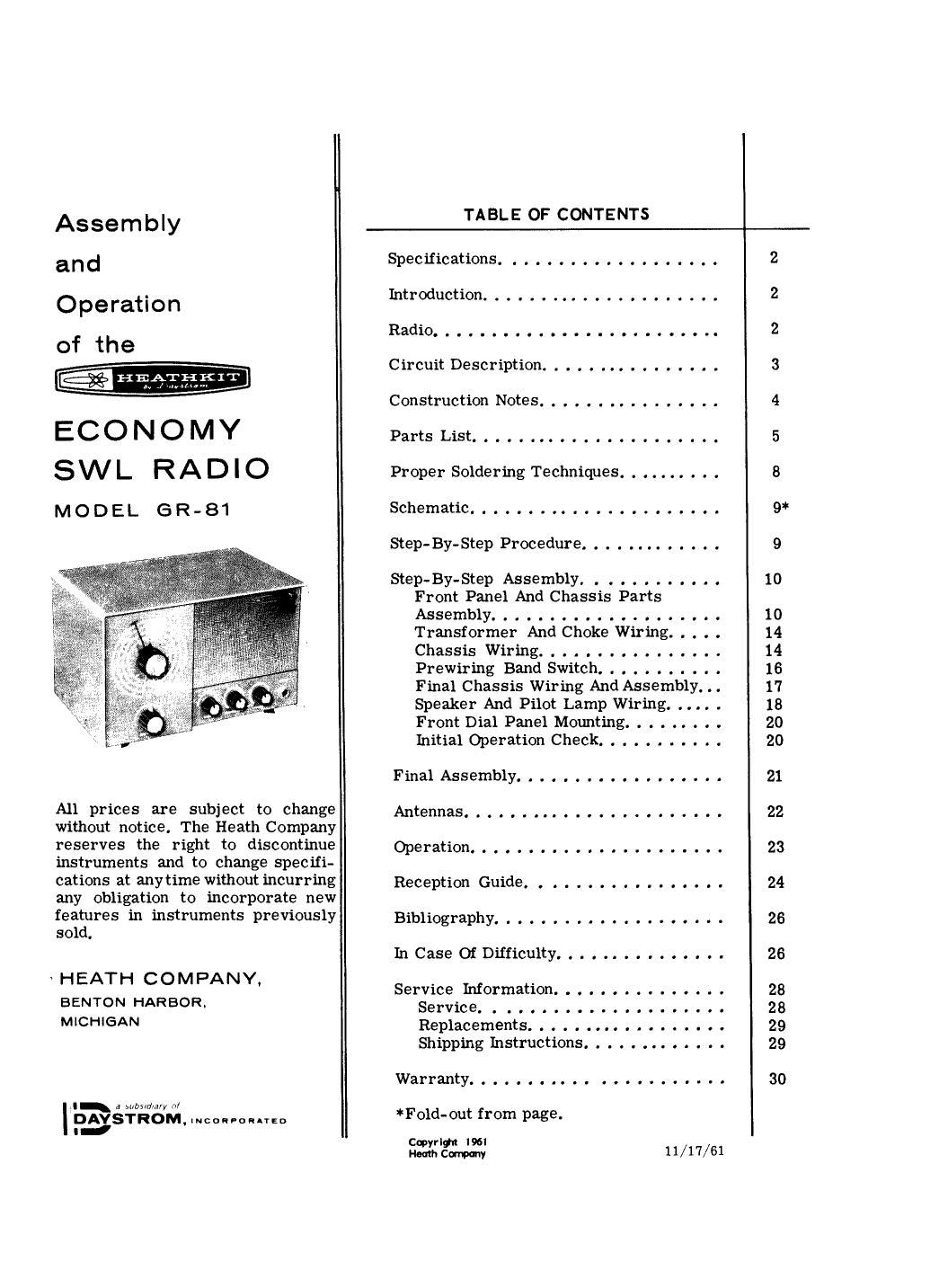
Heathkit GR 81 Schematic

This is the 18 pages manual for Heathkit GR 81 Schematic.
Read or download the pdf for free. If you want to contribute, please mail your pdfs to info@audioservicemanuals.com.

Page: 1 / 18
left right
Heathkit GR 81 Schematic

Extracted text from Heathkit GR 81 Schematic (Ocr-read)


Page 1

Assembly
and
Operation
of the
21s»

ECONOMY
SWL RADIO

MODEL (ER-81

KIT

All prices are subject to change
without notice. The Heath Company
reserves the right to discontinue
instruments and to change specifi-
cations at any time without incurring
any obligation to incorporate new
features in instruments previously
sold.

HEATH COMPANY,

BENTON HARBOR.
MICHIGAN

a whiniwy n/

l
PAVSTROM, mean-ol-IED

TABLE OF CONTENTS

Specifications. . . . . . . . . . . . . .
Introduction. . . . . . . . . .
Radio.................
Circuit Description. . . . . . . . .
Construction Notes. . . . . . .. . . .
PartsList.................
Proper Soldering Techniques. . . . . . . .
Schematic.................
Step-By-Step Procedure. . . . . . . . . . .
Step-By-Step Assembly. . . . . . . . . .
Front Panel And Chassis Parts
Assembly...,............
Transformer And Choke Wiring.

Chassis Wiring.............
Prewiring Band Switch. . . . . . . . .

Final Chassis Wiring And Assembly. .

Speaker And Pilot Lamp Wiring. ..
Front Dial Panel Mounting. . . . .. .
Initial Operation Check. . . . . . . . .
FinalAssembly............-
Antennas.....................
Operation....................
Reception Guide. . . . . . . . . . . .
Bibliography..............,...
InCaseOfDifiiculty.............
Service Information. . . . . . .
Service. .

Replacements. . . . . t . . . .
Shipping Instructions. .


Warranty...........

*Fold-out from page.

varlgl I96!
Hmh cm

11/17/61

Page 2

Page 2

SPECIFICATIONS

Frequency Coverage-
BandA...............
BandB..
BandC...

AudioOutput............

Controls. . . . . . .

Tube Complement. . . . . .. . . . .

Antennalnputs............

Power Requirements. . . . . . . v . .

Dimensions..............

140 to 560 kilocycles.
560 to 1730 kilocycles,
L73 to 5.5 megacycles.
5.5 to la megacycles.

1 watt to speaker (PHONES jack for headphones
or external speaker).

Main Tuning.
FINE TUNING.
BAND.
REGENERATION.
OFF/VOLUME.

l2AT7 detector/ audio amplifier.
50C5 audio output amplifier.
35W4 rectifier.

LONG and SHORT ANTENNA, GROUND.

117 V AC, 50/60 cps only, 30 watts.

10" wide x 7" high x 7" deep.

NetWeight......................... 9-3/4lbs.
ShippingWeight...................... ll-l/Zlbs.
INTRODUCTION

The Model GR-Bl SWL (Short Wave Listener)
Radio has been designed to provide a large
scope of listening excitement from stations of
many parts of the world. The four bands of
frequencies that are covered will allow recep-
tion of the 160, 80, 40, and 20 meter amateur
bands, marine signals, aircraft signals, distress
frequencies, standard broadcasts, government
stations, international broadcasts, etc. The Main

Tuning and FINE TUNING knobs make tuning
simple. There are provisions for a short or a long
antenna to cope with reception characteristics
in various localities, depending on signal fre-
quencies and strengths. The circuit of the Radio
incorporates a filter choke in the power supply
for a low hum level and apower isolation trans-
former to eliminate shock hazards. Normally
common to series string, AC-DC circuits.

RADIO

Radio is a means of sending information through
space from one point to another, without wires
connecting the two points. The different forms
of information transmitted are many andvaried,
but are frequently either sound waves produced
by a voice or an orchestra, or a wave so
interrupted that it is broken into a combination
of long and short groups that correspond to the
characters of the Morse code.

When an announcer speaks into a microphone in
a radio broadcast station, the sound waves cre-
ated by his voice arepicked up bythe microphone
and changed into electrical impulses. The weak
electrical impulses from the microphone are then
fed into atransmitter. The transmitter amplifies
or strengthens the weak signals fromthe micro-
phone and transforms them into an electrical
form that can be fed to an antenna and radiated

Page 16

a15