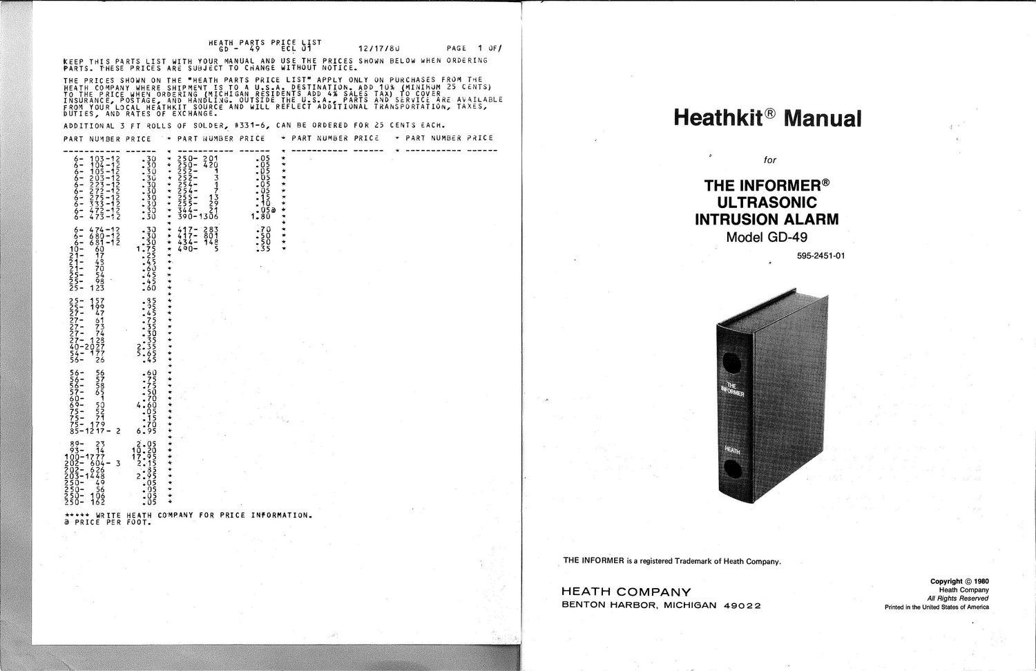
Heathkit GD 49 Manual

This is the 26 pages manual for Heathkit GD 49 Manual.
Read or download the pdf for free. If you want to contribute, please mail your pdfs to info@audioservicemanuals.com.

Page: 1 / 26
left right
Heathkit GD 49 Manual

Extracted text from Heathkit GD 49 Manual (Ocr-read)


Page 1

Heathkit® Manual

, .

for
THE INFORMER®
ULTRASONIC
INTRUSION ALARM

595-2451-01

Mode! GD-49

\ THE INFORMER is a registered Trademark of Heath Company.

Copyright © 1990

Heath Company
All Rights Reserved

Printed in the United States of America

HEAHflCOMPANY

BENTON HARBOR, MICHIGAN 49022

1 OF/

PAGE
SHOWN BELOW WHEN ORDERING

12/17/80

E PRICES
T NOTICE.

U

SE T
ITHO

KP.

RE AVAILABLE
m, TAXES,

RAO
E I

MJM 25 CENTS)

ASES FROM THE

HY OCR
S NED: 0
AC LD

EACH.

CENTS

CAN BE ORDERED FOR 25

ADDITIONAL 3 FT ROLLS 0F SOLDER, #331'6,

NUMBER PRICE * PART NUMBER PRICE

* PART

PART NUMBER PRICE

o

PART NUMBER PRICE

*****V¥+*Q*tfi!v

3
5555555050
0000001108
.... ....-.

1

1013173916
02 1220
77* 1a

1
_ . _ _ . - . . _ _
0022445540
5555555549
2222222233

0005
7553
..7.

_3185

0001*
281

_...
7740
1130
4444

«+.§+*+¢*wt.~fi*té«~x'*.~iv*«tvocw~+wé*~tii+t§<*tifioitv*+

UOUNUOOUPJOU
33.533.53.533
. . . . . c . . . .

2222222222
111111111
. . _ . . . . . . .
3453325323
0000277377
1112222344

._._.__.__
6666666666

0005550550

3337246446

. . . . . . . . . .
1

222
111
.._
4010730483
7886147592
466 1

_ - . _ _ _ . . . _
6660111555
1227.222

5555505555

3947333364

. . . . . . . . . .
25

7071348776

59467727312

11 101
2

. _ . _ _ . . _ . _

5577777045

2222222455

0550005505
6775760179
.uno-lailo

4 6

2

-
6785102197
5556 55771

12

1
_._...<.._
6667095555
5555667778

SUSS-355555
0291890000
. . . . . . . . . .

.207-5 . 7..
11

3

_
3474689662
2170244506

7664 11
1 1
_ . . . . . . _ _ _
9302230000
8900005555
12222222

TH COMPANY FOR PRICE INFORMATION.

T.

E EA
R 00

T H
E F

io¢~w WRI
3 PRICE P

Page 2

is

Page 2

-HEATHKITE
TABLE OF CONTENTS
introduction ........................................ 2 Troubleshooting Chart .............................. 27
Parts List .......................................... 3 Specifications ..................................... 30
Step-by-Step Assembly .............................. 4 Circuit Description ,,,,,,,,,,,,,,,,,,,,,,,,,,,,,,,,, 31
Transformer Primary Wiring ......
Chassis Notes .................. Circuit Board X-Ray Views .......................... 33
Chassis Parts Mounting ........................ 15
Chassis Photograph ................................ 36
Test and Adjustments .............................. 20
Voltage Charts .................................... 37
Final Assembly ................................... , . 22
Schematic ................. (Illustration Booklet. Page 5)
Installation ........................................ 23 ,
, . Warranty ............................ Inside front cover
Operation 25
Alarm Devices ............................. ;'. . . 25 Customer Service ..................... Inside rear cover
In Case of Difficulty ............ . ......... ; ....... '... 26
INTRODUCTION

The Heathkit The lnformer®" Ultrasonic Alarm, Model
GD-49. is primarily intendedto proVide'a warning when a
specific area has been penetratedbyan intruder. This ability to
detect movement Wi , ' A réacan also be used as an
automatic lightswitchf _ rigarage. basement. attic, or
other place where'you wan entry into the area to turn on the
light. it can be used to a buzzer when movement oc-
curs, such as a child '

The Intrusion Alarm is completely inclosed by metal and
can be installed anywhere that an electric outlet is available.
It is also provided With a case which simulates a book cover,
which will help to disguise the identity of the device.

When the Intrusion Alarm has been installed to survey an
area, varying the ultrasonic wava by movement causes a

"lamp" socket to be switched on. Approximately 30
seconds later, an "alarm" socket is switched on. The two
sockets can be switched to automatically turn off after 30
seconds, or to remain on until the Alarm is turned off. The
devices attached to the two sockets are furnished by the
user, and may be of any description, subject only to a total

current limitation of three amperes AC from the two

sockets.

The Intrusion Alarm is simple to build and install. Its solid
state circuitry should provide many years of tremblefree,
economical service. The two outlets permit you to tailor
the protection to the needs of your home or business.

Refer to the Kit Builders Guide for information on tools,
wiring, soldering, resistors, and capacitors.

-HEATHKITa

Page 3

PARTS LIST

This Parts List" contains all of the parts used in the
assembly of the kit. Some parts may be packaged in
envelopes with the part number of the contents printed on
the outside. Except for the initial parts check, retain these
parts in their envelopes until they are called for in the
assembly steps. When more than one number is on a

.package, disregard all but the part number listed in the

Parts List.

KEY PART PARTS DESCRIPTION
No. No. Per Kit

RESISTORS, 1/4-WATT
5% Tolerance (4th band gold)

A1 6-680-1 2 3

68 fl (blue-gray-
black)

A1 6-681-12 7 660 n (blue-gray-
Brown)

A1 6-272-12 1 2700 0 (red-Violet-
red)

A1 6-47212 4 4700 0 (yellow-violet-
red)

A1 6-103-12 11 10 k0 (brown-black-
orange)

A1 6-203-12 4 20 kn (red-black-
orange)

A1 6-223-12 4 22 k0 (red-red
orange)

A1 6-333-12 4 33 kt) (orange-orange-
orange)

A1 6473-12 6 47 kn (yellow-violet-
orange)

A1 6-104-12 6 100 kn (brown-black-
yellow)

A1 6-474-12 2 470 k9. (yellow-violet-
yellow)

A1 6-105-12 3 1 MS) (brown-black-
green)

A1 6-275-12 1 2.7 MG (red-violet-
green)

CONTROL

A2 10-60 1 500 kfl

Check each part against the following list. The key numbers
correspond to the numbers on the Parts Pictorial (Illustration
Booklet. Page 1).

To order a replacement part. use the Parts Order/Form fur-
nished with this kit. If a Parts Order Form is not available. refer
to Replacement Parts inside the rear cover of the Manual.
For prices. refer to the separate Heath Parts Price List."

KEY PART PARTS DESCRIPTION

No. No. Per Kit

CAPACITORS

Disc

A3 21-17 3, 270 pF

A4 21-70 2 .01 pt, 1.4 KV

A4 21-48 2 .05 MF

Electrolytic

A5 25-123 4 2 F

A5 25-54 2 10 uF

A6 2598 4 50 ,uF

A7 25-157 1 500 F, 15V

A7 25-199 1 500 uF, 25V

Mylar*

A8 27-74 3 .01 HF (.01 K)

A8 27-128 2 .022 ,uF

A8 27~73 3 .047 uF

A9 27-47 1 .1 F

Other

A10 27-61 1 .47 HF polystyrene

DIODES

Bi 56-26 2 1N191 (brown-white-
brown)

B1 5658 3 1N709A

Bi 56-57 1 1N716A (violet-brown-
bluebrown)

B1 57-65 4 1N4002

B1 5656 2 1N4149

DuPont Company Registered Trademark