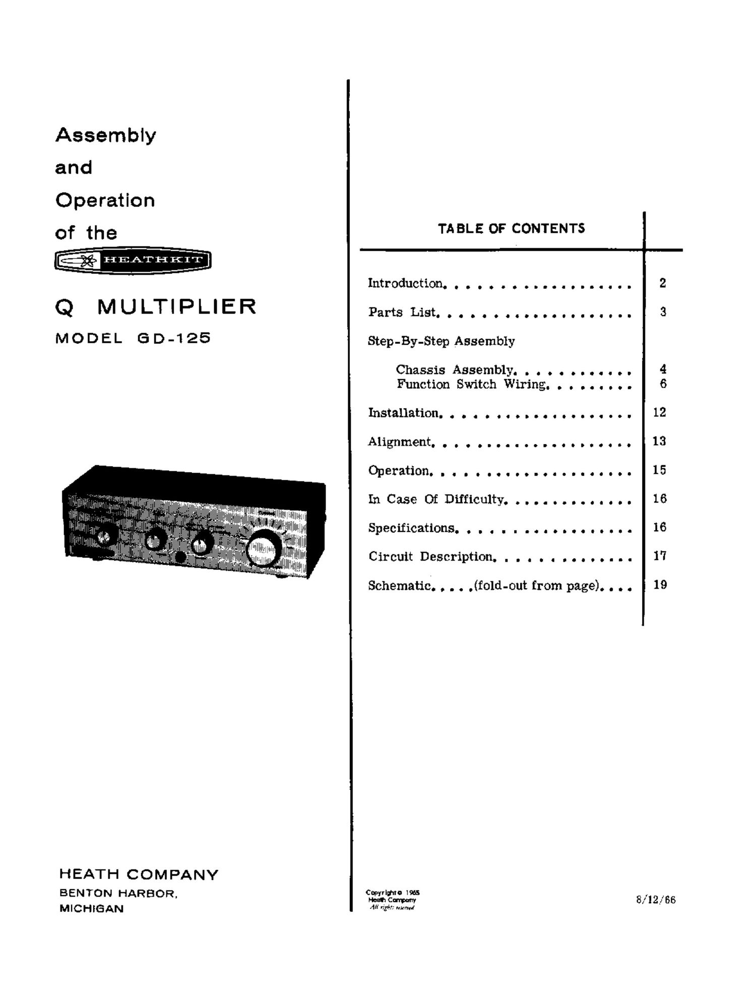
Heathkit GD 125Q Schematic Manual

This is the 10 pages manual for Heathkit GD 125Q Schematic Manual.
Read or download the pdf for free. If you want to contribute, please mail your pdfs to info@audioservicemanuals.com.

Page: 1 / 10
left right
Heathkit GD 125Q Schematic Manual

Extracted text from Heathkit GD 125Q Schematic Manual (Ocr-read)


Page 1

Assembly

and
Operation
of the TABLE OF CONTENTS
-HEATHKIT
Introduction................... 2
Q MULTIPLIER PartsList.................... 3
M O D EL 6 D -1 25 Step-By-Step Assembly
Chassis Assembly. . . . . . . . . . . . 4
Function Switch Wiring. . . . . . . . . 6
Installation.................... 12
Alignment..................... 13
Operation..................... 15
InCaseOfDiIficulty.............. 16
SpecificathHS.................. 16
Circuit Description. . . . . . . . . . . . . . 1'?
Schematic. . . . .(fold-out from page). . . . 19
HEATH COMPANY
BENTON HARBOR. fig? 8,1291%

M I C H 3 AN M #36:,- mam!

Page 2

Page 2

am

INTRODUCTION

The Heathkit Model GD-125 Q Multiplier is used
with communications receivers to provide addi-
tional selectivity and signal rejectiOn. Because
its peak or null effect can be tuned across the
receiver IF bandpass, the operation of the Q
Multiplier is more flexible than that of a fixed
frequency IF filter. :

The Q Multiplier may also be used with a re-
ceiver which already has an IF filter, to obtain
two simultaneous functions. For example, the
IF filter could be set to peak the desired
signal and the Q Multiplier used to null an
adjacent signal.

When properly connected and adjusted, the Q
Multiplier will not decrease receiver sensitivity.

In the peak function, an audible gain will be noted
on CW signals, and a carrier gain will be noted
on the S meter for phone signals. However, the
audio will be attenuated slightly due to narrowing
of the received sidebands.

The reduced sideband reception will tend to
attenuate the higher audio frequencies. This
is more than compensated for by the increased
readability against the surrounding QRM.

NOTE: Refer to the "Kit Builders Guide" for
complete information on unpacking, parts identi-
fication, tools, wiring, soldering, and step-by-
step assembly procedures.

Page 9

Page 16

HEATI-IICIT

IN CASE OF DIFFICULTY

NOTE: Refer to the Kit BuildersGuide for Serv-
ice and Warranty information.

1.

Operating Frequency. a . Clo-GIIOI... .0
Switch Functions. ...................

Tube -Diode Complement.

Power Requirements............ .....
cabinet8128..................ouauooc

NEt Weightgo.gooooonolocovochOOOI

Recheck the wiring. Trace each lead in
colored pencil on the Pictorial as it is
checked. It is frequently helpful to have a
friend check your work. Someone who is not
familiar with the unit may notice something
consistently overlooked by the constructor.

It is interesting to note that about 90%01 the
kits that are returned for repair, do not
function properly due to poor connections
and soldering. Therefore, many troubles
can be eliminated by reheating all connec-
tions to make sure that they are soldered
as described in the Soldering section of
the Kit Builders Guide.

Make sure that the tube lights up properly.
Check the tube with a tube tester or by

substitution of a tube of the same type
and known to be good.

5'

Check the values of the component parts.
Be sure that the preper part has been
wired into the circuit, as shown in the

pictorial diagrams and as called out in the
wiring instructions.

Check for bits of solder, wire ends or other
foreign matter which may be lodged in the
wiring.

If, after careful checks, the trouble is still
not located and a voltmeter is available,
check voltage readings against those found
on the Schematic Diagram. NOTE: All
voltage readings were taken with an 11 meg-
ohm input vacuum tube voltmeter. Voltages
may vary as much as 10% due toline voltage
variations.

A review of the Circuit Description will
prove helpful in indicating where to look
for trouble.

Make sure the receiver that is being used
with the Q Multiplier has an IF between
450 and 500 kc.

SPECIFICATIONS

450 - 500 RC.

OFF, PEAK, NULL, BROAD.

1 - 12AX7 tube, multiplier.
1 - Silicon diode, rectifier.

105-12 5 volts AC,

50/60 ops, 4-1/2 watts.

9-1,.32" wide x 2-9/16" high x 3-5/8 deep.

2 -1/2 1138.