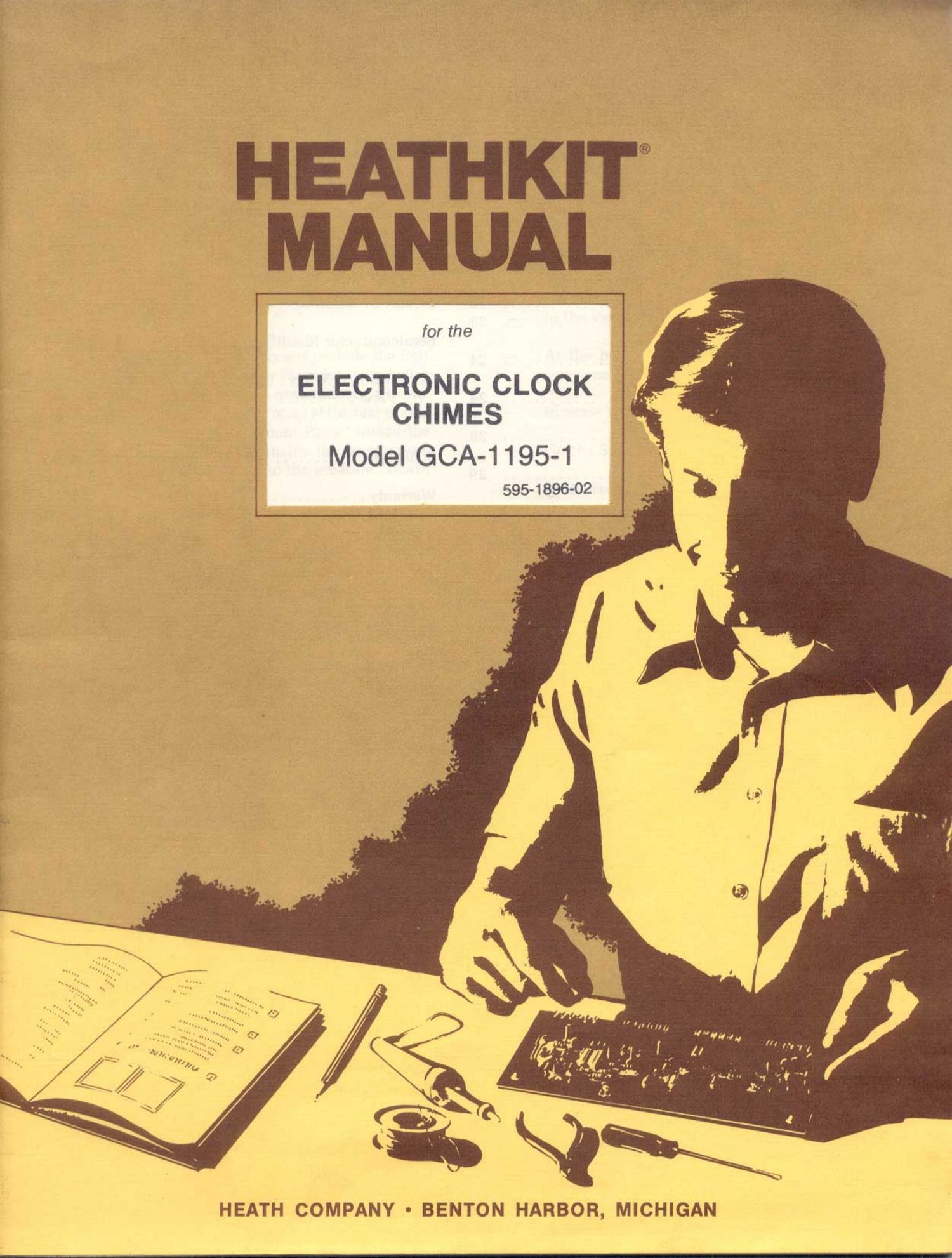
Heathkit GCA 1195 1 Manual

This is the 40 pages manual for Heathkit GCA 1195 1 Manual.
Read or download the pdf for free. If you want to contribute, please mail your pdfs to info@audioservicemanuals.com.

Page: 1 / 40
left right
Heathkit GCA 1195 1 Manual

Extracted text from Heathkit GCA 1195 1 Manual (Ocr-read)


Page 1

HEATHKIT®
MANUAL

HEATH COMPANY - BENTON HARBOR, MICHIGAN

Page 2

Heathkit® Manual

for the

ELECTRONIC CLOCK
CHIMES

Model GCA-1 195-1

595-1 896-02

Copyright © 1978
Heath Company

HEATH COMPANY All Rights Reserved
BENTON HARBOR, MICHIGAN 49022 anedmtheUnfledStatesofAmerica

Page 28

Pa 6 27
_HEATHKIT~I g

While you hold the test lead on the collector of
0302. FAST advance the clock display through
a one-hour transition [for example. advance the
display from 3:08 to 4:08). The LED should light
and then slowly go off again.

TIC-TOC SYNTHESIZER ( l

( ) Touch the test lead to IC314 pins 1 and 13. The
LED should flash slowly.

POSSIBLE CAUSE CHART

POSSIBLE CAUSE CHART

The LED lights and stays lit.
The LED does not light.

LED does not light.

LED lights but does not flash.

A. [(3314.

A. 0302.

B. D306, D307, D308, D309, or D311.

C. R326, R327. R328, R329. R331. or R332.
D. C307 or C308.

Touch the test lead to the banded end of D304
and D305. The LED should light.

LED does not light.
LED lights at full intensity. ( )

A. IC315 or IC314.
B. D304 or D305.
C. R322.

( ) Touch the test lead to IC31 5 pins 10 and 1 1. The
LED should flash dimly at a slow rate.

LED does not light.
LED does not flash.

LED flashes at full intensity.

A. lC315.
B. C303 01 C304.
C. R315 or R316.

CHIMES SYNTHESIZER

NOTE: In some of the following steps, you will be

instructed to set the clock display between quarter ( )

hours. This means to set the display to any time other
than on the hour. 15 minutes after the hour. 30 min-
utes after the hour. or 45 minutes after the hour.

( )

quarter hours and wait approximately one min-
ute. Then touch the test lead to the collector of
0302. The LED should not light.

Advance the clock diSplay to any time between ( )

Advance the clock display to any time between
quarter hours and wait approximately one min-
ute. Then touch the test lead to the collector of
0303. The LED should not light.

While you hold the test lead on the collector of
0303. FAST advance the clock diSplay through
a one-hour transition. The LED should light and
then slowly go off again.

LED lights and stays lit.
LED does not light.

A. 0303.

B. D312. D313. D314. D315, or D316.

C. R333, R334, R335, R336, R337. or R338.
D. C309 or C311.

Advance the clock display to any time between
quarter hours and wait approximately one min-
ute. Then touch the test lead to the collector of
0304. The LED should not light.

While you hold the test lead on the collector of
0304, FAST advance the clock display through
a one-hour transition. The LED should light and
then slowly go off again.

Page 31

Page 30

_HEATHKIT'

IN CASE OF DIFFICULTY

This part of the Manual will help you locate and
correct any difficulties which might occur. This in-
formation is divided into:

Visual Checks
Precautions for Bench Testing
Troubleshooting Chart

NOTES:

1. In an extreme case where you are unable to
resolve a difficulty. refer to the Customer Ser-
vice" information inside the rear cover of the
Manual. Your Warranty is located inside the
front cover.

2. For the physical location of parts on the circuit
board. refer to the Circuit Board X-Ray View"
in the Illustration Booklet."

VISUAL CHECKS

1. About 90% of the kits that are returned for re-
pair do not function properly due to poor sol-
dering. Therefore, you can eliminate many
troubles by a careful inspection of connections
to make sure they are soldered as described on
Page 9 of this Manual. Reheat any doubtful
connections and be sure all the wires are sol-
dered at places where several wires are con-
nected. Check carefully for solder bridges bet-
ween circuit board foils.

2. Make sure all transistors and diodes are in their
proper locations, and are installed correctly.

3. Check the value of each part. Be sure the proper
part has been wired into the circuit, as shown in
the Pictorial diagrams and as specified in the
wiring instructions. It would be easy, for exam-
ple, to install a 10 k0 (brown-black-orange) re-
sistor in a step that calls for a 100 k!) (brown-
black-yellow) resistor.

4. Recheok the wiring. Trace each lead in colored
pencil on the Pictorial as you check it. It is
frequently helpful to have a friend check your
work. Someone who is not familiar with the
unit may notice something you have consis-
tently overlooked.

5. Check all of the wires that are connected to the
circuit board to be sure they do not touch the
chassis or other lugs. Make sure all wires are
properly soldered.

6. A review of the Circuit Description" may help
you determine the problem.

7. If the difficulty still is not cured, read the "Pre-
cautions for Bench Testing section. and the
section titled "Troubleshooting Chart.

PRECAUTIONS FOR BENCH TESTING

NOTE: Use a high input impedance voltmeter for
voltage measurements.

1. Be cautious when you test transistor circuits.
Although transistors have almost unlimited life
when used properly, they are much more vul-
nerable to damage from excessive voltage or
current than other circuit components.

2. Be sure you do not short circuit any terminals
when you make voltage measurements. If the
probe should slip, for example, and short out a
bias or voltage supply point. it is almost certain
to damage one or more transistors or diodes.

3. Do not remove any components while the kit is
operating; this could cause considerable dam-
age.

If you make repairs to your Chimes, make sure you
eliminate the cause as well as the effect of the trouble.
If, for example, you should find a damaged resistor, be
sure to find out what caused the resistor to become
damaged. If the cause is not eliminated, the replace-
ment resistor may also become damaged when the
unit is put back into operation.