Heathkit EUW 19A Schematic

This is the 3 pages manual for Heathkit EUW 19A Schematic.
Read or download the pdf for free. If you want to contribute, please mail your pdfs to info@audioservicemanuals.com.

Page: 1 / 3
left right
Heathkit EUW 19A Schematic

Extracted text from Heathkit EUW 19A Schematic (Ocr-read)


Page 1

Page 2

H E A'I'H

SPECIFICATIONS

Contents of System ................ . . . .

Four Differential Input Operational Amplifiers.
One Booster Amplifier.

One DC+ Power Supply, regulated,

One DC- Power Supply, regulated,

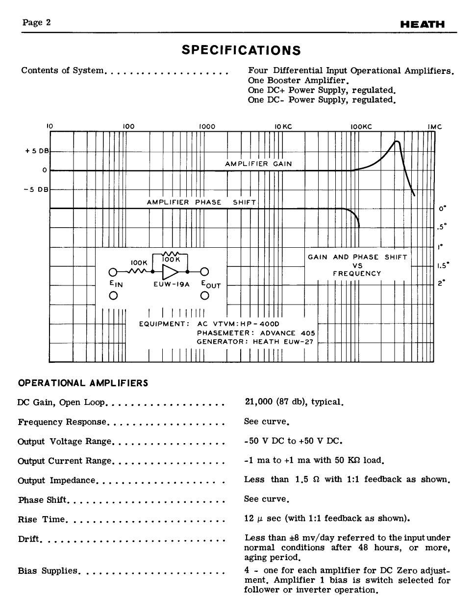
I0 I00 Iooo Io KC IOOKC IMC
+ 5 DB /\
I
o AMPLIFIER GAIN
-5 DB
AMPLIFIER PHASE SHIFT .
0
~
.5"
I.
IOOK IOOK GAIN AND CSASE SHIFT L5.
-0 FREQUENCY
EIN Euw-IgA Eour 2'
O O
I | I l l I III
EQUIPMENT: AC VTVM:HP-4OOD
PHASEMETER: ADVANCE 405
GENERATOR: HEATH Euw-27

OPERATIONAL AMPLIFIERS

DC Gain, Open Loop ..... . . . . . . . . . . . . . 21.000 (37 db), typical,

Frequency Response ......... . . . ....... See curve,

Output Voltage Range .................. -50 V DC to +50 V DC.

Oatput Current Range ..... . . ........... -1 ma to +1 ma with 50 K9 load,

Output Impedance ............ . ...... . Less than 1.5 Q with 1:1 feedback as shown,

Phase Shift. . . . . ...... . ............. See curve.

Rise Time ........... . ..... . ....... 12 I.I see (with 1:] feedback as shown).

Drift. ...... . . .................... Less than 16 mv/day referred to the input under
normal conditions after 48 hours, or more,
aging period.

Bias Supplies. ...................... 4 - one for each amplifier for DC Zero adjust-

ment, Amplifier 1 bias is switch selected for
follower or inverter operation.

Page 2

HEATH

Page 3

BOOSTER AMPLIFIER
Maximum Output .................. . . .
Gain. . . . . . . . ........... . .........

Output Impedance .....................

+300 V AND -300 V REGULATED
POWER SUPPLIES

DC+ Output Voltage Range ...............
DC- Output Voltage Range ...............

Voltage Regulation (Each Supply) ..........

Ripple Voltage (Each Supply). . . . . . . . .....

Output Impedance (Each SUpply) ...........

POWER REQUIREMENTS

AC Input ...........................
Filament Power Only .......... . .......
Total Power Required ....... . ........ . .
Fuses............. ....... . ..... ..

AUXILIARY POWER CONNECTOR

Location ........................ . . .

Power Available ....... . ...... . ......

Balance Resistors .................. . .

GENERAL

Dimensions. . . . . ......... . .........
Net Weight ........ . . . . .
Shipping Weight ......................

:20 ma at 50 V DC.
Approximately 0.8.

Less than 0.2 9.

Regulated +275 to +325 volts (approximately).
Regulated -275 to -325 volts (approximately).

Output variation less than 1% from no load to
full load at 300 volts. Output variation less
than *1 volt for a 110 volt variation in the AC
line input.

Less than 10 millivolts rms ripple, jitter, and
noise.

Less than 10 o from 5-100,000 cps.

105-125 volts, 50/60 cps.
44 watts.
94 watts at quiescent operating conditions.

Two 3/4 ampere slow-blow fuses; one for the
filament circuits, and one for the DC+ and DC-
supplies.

Octal socket on rear of unit, and banana jacks
on front panel,

+300 volts at 20 ma and -300 volts at 20 ma with
unit in operation, +300 volts at 60 ma and ~300
volts at 60 ma when all amplifier tubes are
removed. 6.3 volts AC at 50 ma with unit in
operation. 6.3 volts AC at 3.2 amperes with all
amplifier tubes removed.

Available at auxiliary connector to balance
power supplies.

11-1/4" wide x 6-3/8" high x 12-7/8" deep.
15-3/4 lbs,
1'? lbs,

All prices are subject to change without notice.
The Heath Company reserves the right to disc on-
tinue instruments and to change specifications at

any time without incurring any obligation to
incorporate new features in instruments pre-
viously sold,