Heathkit EUW 17 Schematic

This is the 2 pages manual for Heathkit EUW 17 Schematic.
Read or download the pdf for free. If you want to contribute, please mail your pdfs to info@audioservicemanuals.com.

Page: 1 / 2
left right
Heathkit EUW 17 Schematic

Extracted text from Heathkit EUW 17 Schematic (Ocr-read)


Page 1

Page 2 H E ATl-l

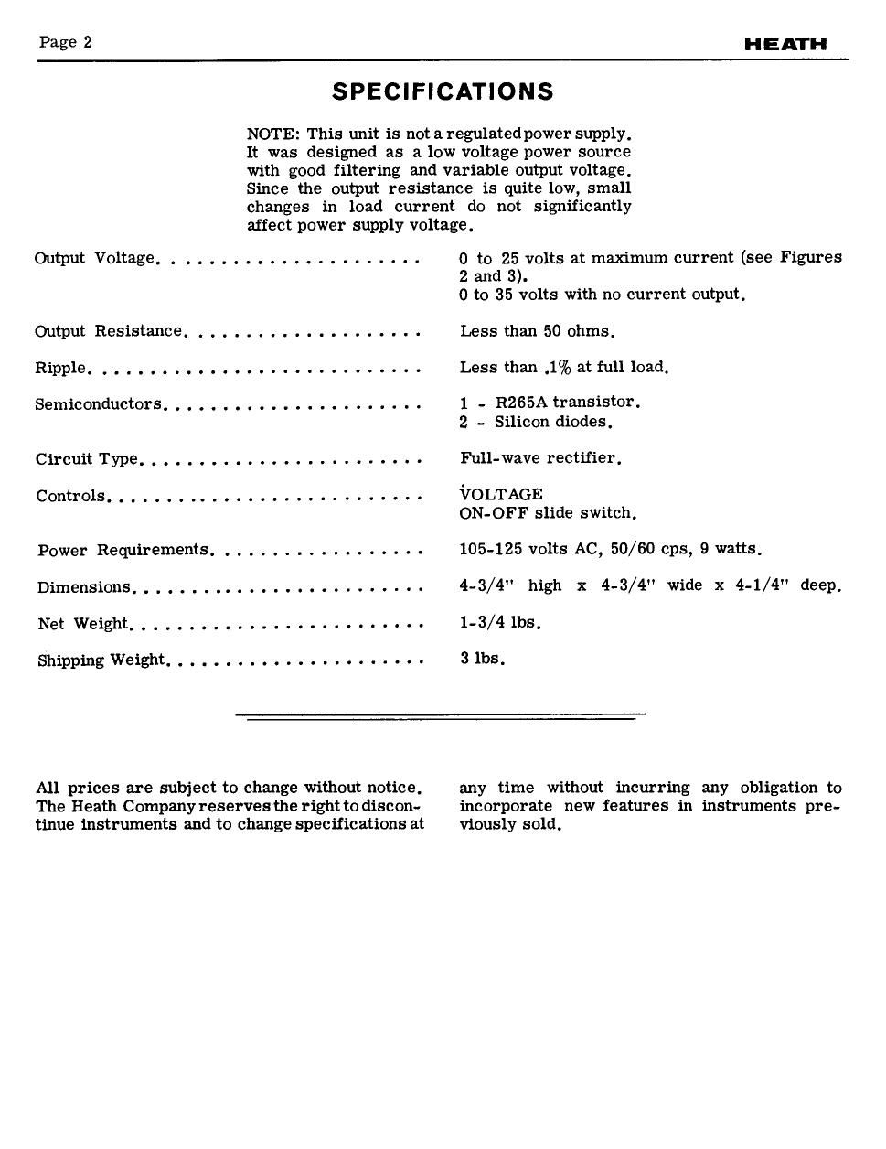
SPECIFICATIONS

NOTE: This unit is not aregulatecl power supply,
It was designed as a low voltage power source
with good filtering and variable output voltage.
Since the output resistance is quite low, small
changes in load current do not significantly

affect power supply voltage.

Output Voltage. . . ................... 0 to 25 volts at maximum current (see Figures
(2) :ggbolts with no current output.
Output Resistance .................... Less than 50 ohms.
Ripple . . . . . . . ........... . ....... Less than .1% at full load.
Semiconductors. . . . . . . ....... . . 1 - R265A transistor.
2 - Silicon diodes.
Circuit Type. . . ..................... Full-wave rectifier.
Controls. . . . . . . ....... . ............ VOLTAGE
ON-OFF slide switch.
Power Requirements .................. 105-125 volts AC. 50/60 cps, 9 watts.
Dimensions. . . . . . . . ...... . . ......... 4-3/4" high x 4-3/4" wide x 4-1/4" deep.
NetWeight..... ..... ..... 1-3/41bs_
Shipping Weight. . . . . . ......... . ...... 3 lbs.

All prices are subject to change without notice.
The Heath Company reserves the right to discon-
tinue instruments and to change specifications at

any time without incurring any obligation to
incorporate new features in instruments pre-
viously sold.

Page 2

HEATH

Page 7

CIRCUIT DESCRIPTION

Refer to the Schematic Diagram while reading
this description,

The AC output voltage from the power trans-
former is rectified by a full-wave rectifier that
consists of two silicon diodes, The rectified
voltage is then filtered by a 500 ufcl capacitor
and applied to an electronic filter circuit.

The electronic filter circuit consists of the
transistor, the remaining 500 ufd capacitor,
and the biasing and current limiting resistors,
In this circuit the filtering action of the 500 Md
capacitor in the base circuit of the transistor is
multiplied by the gain of the transistor, In this

case, where the gain of the transistor is about
50X, the 500 ufd capacitor in the base circuit
has the same effect that a 25,000 ufd (50X500
hid) capacitor would have at the output termi-
nals.

The 5000 (2 control varies the bias of the tran-
sistor which changes the emitter to collector
resistance of the transistor. Increasing and de-
creasing this transistor resistance increases or
decreases the amount of voltage available at the
output terminals. The 3300 Q resistor acts as
a bleeder and also applies operating current to
the transistor under no-load conditions. The
.l ufd capacitor filters out any noise pulses
present in the power supply.

H O
+
500
OF F MD
105-125 25 VAC .1:
VAC 50v
__-1UFD o»25 v
Eov oizAMp MAX
25 VAC
0

R265A

I/2 AMP

SCHEMATIC OF THE
HEATH SCIENCE SERIES
TRANSISTOR POWER SUPPLY
MODEL EUW-I7