Heathkit EUW 15 Schematic

This is the 2 pages manual for Heathkit EUW 15 Schematic.
Read or download the pdf for free. If you want to contribute, please mail your pdfs to info@audioservicemanuals.com.

Page: 1 / 2
left right
Heathkit EUW 15 Schematic

Extracted text from Heathkit EUW 15 Schematic (Ocr-read)


Page 1

Page 2

HEATH

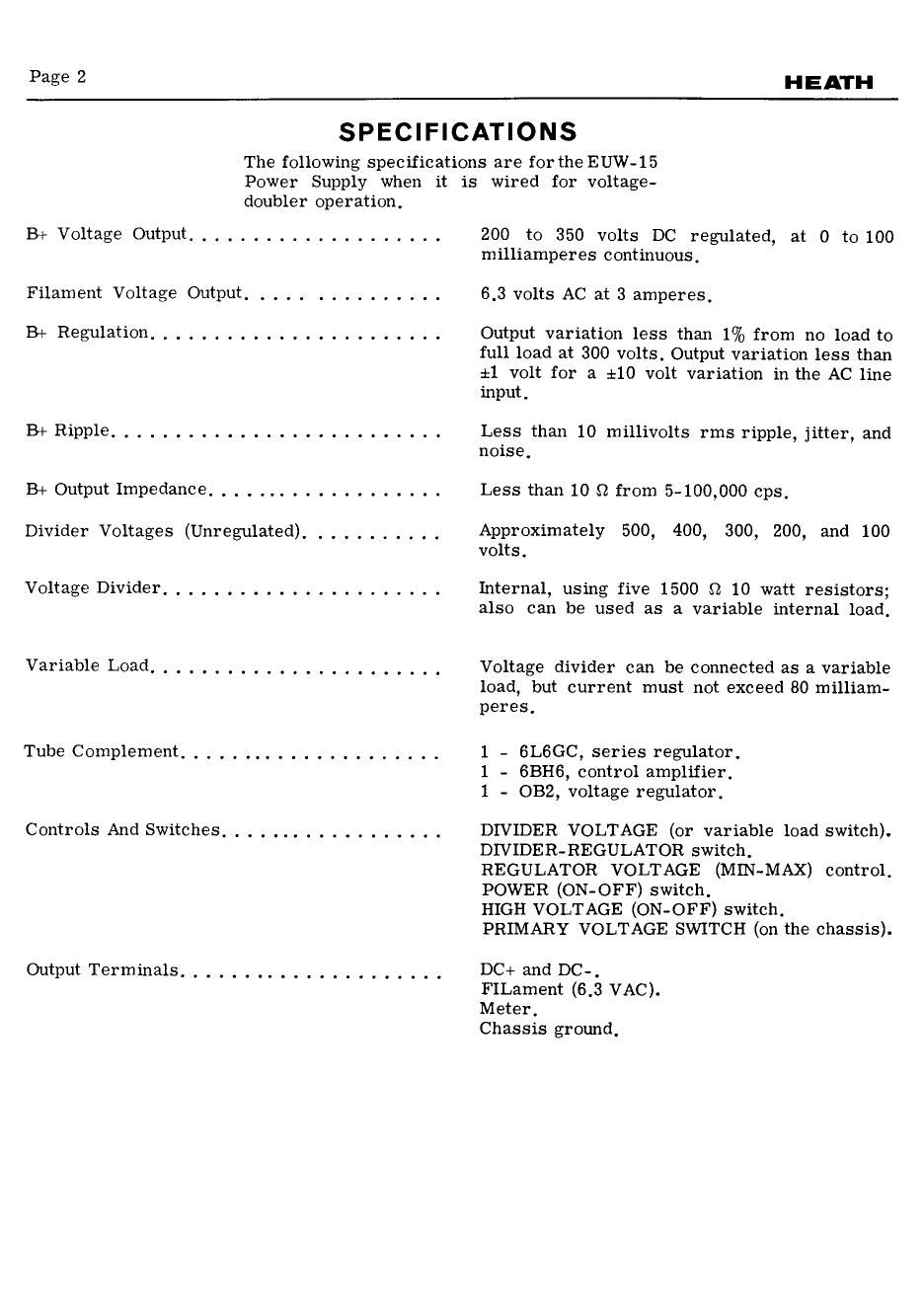
SPECIFICATIONS

The following specifications are for the EUW-15
Power Supply when it is wired for voltage-

doubler operation,

B+ Voltage Output ....................

Filament Voltage Output ...............

B+ Regulation. ,

B+Ripp1e .....
B+ Output Impedance. . . . ............
Divider Voltages (Unregulated) ........ , . .
Voltage Divider ..... . . . ......... . . . . .
VariableLOad..... ..... . .....

Tube Complement,

Controls And Switches. . . . . .. . . . .

Output Terminals ........ . . . . . ........

200 to 350 volts DC regulated, at 0 to 100
milliamperes continuous.

6.3 volts AC at 3 amperes,

Output variation less than 1% from no load to
full load at 300 volts. Output variation less than
:1 volt for a $10 volt variation in the AC line
input.

Less than 10 millivolts rms ripple, jitter, and
noiSE.

Less than 10 $2 from 5-100,000 cps,

Approximately 500, 400, 300, 200, and 100
volts.

Internal, using five 1500 o 10 watt resistors;
also can be used as a variable internal load.

Voltage divider can be connected as a variable
load, but current must not exceed 80 milliam-
peres.

1 - GLGGC, series regulator.
1 - 6BH6, control amplifier,
1 - 0B2, voltage regulator.

DIVIDER VOLTAGE (or variable load switch).
DIVIDER-REGULATOR switch,

REGULATOR VOLTAGE (MIN-MAX) control.
POWER (ON-OFF) switch.

HIGH VOLTAGE (ON-OFF) switch.

PRIMARY VOLTAGE SWITCH (on the chassis).

DC+ and DC-,
FILament (6.3 VAC).
Meter.

Chassis ground.

Page 2

HEATH

POWER
TRANsroRMER

aL K- (.RN
.

«05- I25

VAC so H/z AMP
.

Ac PUWER
' N

a
or;

o
SLOW-BLOW
FUSE

Page 11

REGULATOR DIVIDER

fir?)

W

z F-CK e
we AMP smwi
BLOW FUSE

HIGH
VOLTAGE

I
I
4
i
I

-
max

VOLTAGE ,
ADJusT

ELOw rusE

I/B AMP wows

SCHEMATIC OF THE
HEATH SCIENCE SERIES
UNIVERSAL POWER SUPPLY
MODEL EUW-IS

NOIES:

ALL RESISToRS ARE I/z WATT UNLESS SHOWN OTHERWISE,
ALL RESISTOR VALUES ARE IMO, I K :10009, I MEG = 1,000,000 :1,

ALL CAPACITOR VALUES ARE IN Ind UNLESS SHWN OTNERWISEI
DOYTED LINE$ INDICATE CLIP-ON CONNECTING WIREsI

O INDICATES A VOLTAGE MEASUREMENT FROM POINT
INDICATED TO Dc-. EXCEPT FOR Ac VOLTAOES ON

YNE POWER TRANSFORMER AND AC OUTPUT LUGSI

VOLTAGE READINGS TAKEN WITH AN II MEOONM INPUT VTVM

WITH THE CIRCUIT CONNECTED AS SHOWN.

VOLTAOES MEASURED IN REGULATOR POSITION, REGULATOR SET
FOR 300 v OUTPUT, No LOAD

CAPACITOR C3 ACTUALLV CONSISTS OF Two so Ara
CAPACITORS IN SERIES