Heathkit DX 60 Assembly Manual

This is the 32 pages manual for Heathkit DX 60 Assembly Manual.
Read or download the pdf for free. If you want to contribute, please mail your pdfs to info@audioservicemanuals.com.

Page: 1 / 32
left right
Heathkit DX 60 Assembly Manual

Extracted text from Heathkit DX 60 Assembly Manual (Ocr-read)


Page 1

LE COPY 00.91111 i4 :"'..~;L

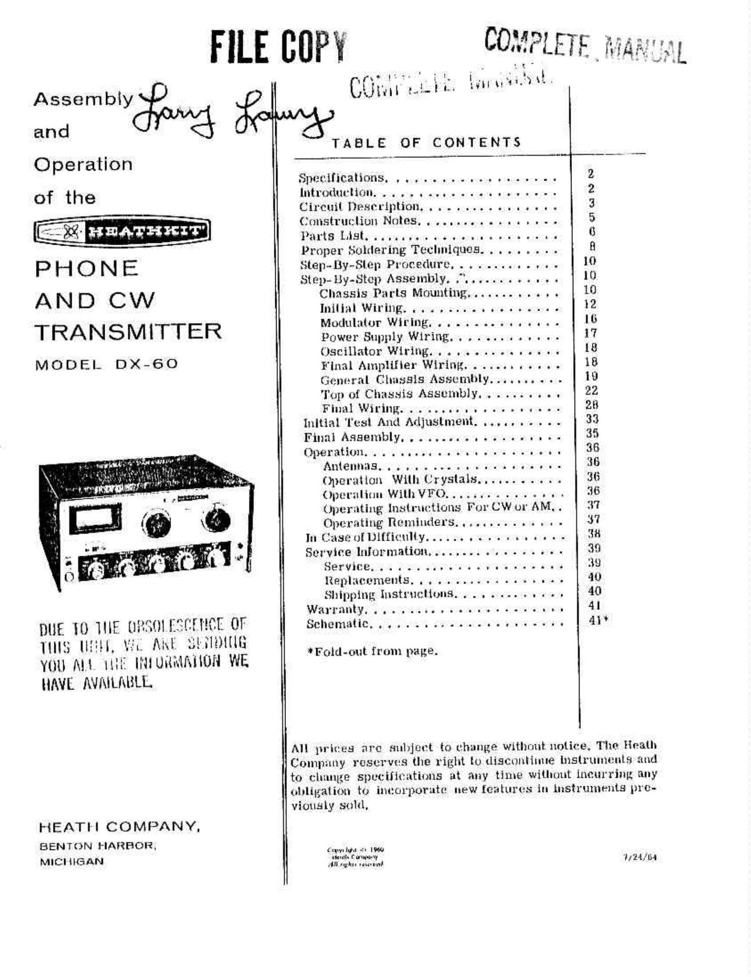
Assembly
and
Operation
of the

PHON E
AN D CW
TRANSMITTER

MODEL DX- 60

DUE l0 lllE il"1flll["l'{l OF
THIS Iliill, 1J1. Ml illll'ellllli
Yllll All 11H? IlllUilis'lMlUll WE
HAVE AVRILMSLL

HEATl-l COMPANY,

BENTON HARBOR,
MICI HGAN

(1!3 '

' ' 1 .4111
Ulnl 1-1-11. .1111

TABLE OF CONTENTS

Specifications. . . . ..... . . . ....... 2
lntmdurlnm. . . . . . .. . . . . . . . . ..... 2
Circuil Description. .......... . . . . . 3
(.11115llur:liunanes................. 5
Pants [Hist . .. ..... . . ..... . 0
Prnpei Soldering Techniques. . . . . E]
Step-By- -Siep P1 ncedure. . . . .. .. . . 10

Step-ily~st0p Assembly. . . . .. . . . . 10

Chassis Parts Mounting... . . .. . . . . 10
Inillnl Wiring. . . . . . . . . . . . ...... 2

Modulator Wiring. . . ...... . . . . . . Iii
Powar Supply Wiring. . . . . .. . . . . . . 17
Oscillator Wiring. . . . . . .. . . . . . . . 13
Final Amplifier Wiring. . . . . . . . . . 18
Gelmrai Chassis Assembly. . . . . . . . . . 13
T111101 Chassis Assembly. . . . . . . 23

Final Wir..lng . . . ... . . . . .. 23
Initial [Isl And Adjustment. ..... 33
FinalAfiaembly...........m........ 35
Operation ..... . . . . ...... . . . . 35

A111ennns....... 35

Operation Will1(.'ryslals...... . . . . . 36

(1.11111 .1111". With VFO. ........ . 36

Upcr rating iii-111111 tiunb Fm CW 111 AM. . 'l'?
Opcj 111111113 1111111111618. .... . . . . . . . . . 37

In (Just: 11[l.)l[ficully ..... . . . . . . . . . . . . 33
Service hIIoimali011.. ...... . . . . . . . . . 39
Service ........ . . . . . . . ...... . 1W

Replacements. . . . . . . . . . . . . . . 40
Shipping Instructions. . . . . . . . . . 40

Warrnnly............... ..... 4|
Schematic. . . ............ . . . . . .. 41

* Fold-out from page.

All 11rl1: us :11 a subject to change with-mt xioii1- e The Heath
Company 1051:1'111- s the 1igl1i lo discontinue [11511111111 11151 and
to change spuciin atinns at any time willmnt lncm r1111. nny
(ulullgalion to incorporate new features in instruments pre-
viously sold,

11.111- 110 .:1 I900
mum fawn-v, , . , .
.0141». mm: UM, In

Page 23

The cathode and grid currents of the final
amplifier are measured with a 0-1 ma meter.
The appropriate shunt, R10 and R11 for grid
current, or R13 for cathode current, is se-
lected by the METER switch, located on the
front panel.

SPEECH AMPLIFIER

Speech amplifier V5 operates as a conventional
resistance coupled audio amplifier. The plate
of V5 is coupled to one-half of modulator
tube V4 through capacitor C33.

MODULATION

Modulator tube V4 contains two dissimilar
triodes, one having a power rating of 1.5 watts
and the other 7 watts. The lower power section
is used as a direct coupled driver to excite
the higher rated section, which is actually
the modulator. The cathode of the modulator
section is coupled to the screen grid of V3, the
final amplifier tube, through R32 and C35.

V4 is so biased that with no audio signal the
conduction of the tube is limited. This allows the
screen voltage of V3 to remain at a low value,

thus limiting the plate current of V3 to a low
resting state.

With modulation applied, conduction in the modu-
lator section of V4 increases, raising the
screen voltage of V3. This results inanincrease

in final plate current with modulation producing
a controlled-carrier effect.

POWER SUPPLY

The power supply section uses four silicon
diodes in a voltage-doubler circuit. Filtering is
accomplished by capacitors C38, C37, C38, and
resistors R18 and R19.

Bias voltage for grid block keying is developed by
a silicon diode in a half-wave rectifier circuit.

A separate 6.3 volt, 4 amp winding for VFO
filaments or other accessory equipment is
available at the accessory power socket.

The line cord uses a fused plug for protection in

the event of short circuits or transmitter over-
load.

GRID BLOCK KEYING

In order to explain grid block keying, it is
necessary to consider key-up and key-down
conditions. Refer to the following partial sche-
matic diagram.

VI 03C. V2 DRIVER
W W

gm as

1, KEY as

V3 FINAL AM
-M/\r--

GRID BLOCK KEYING

KEY-UP

A negative voltage is placed on the grids of tubes
V1, V2, and V3. Since this bias voltage cuts
these tubes off, there can be no transmitter
output.

KEY-DOWN

Under this condition, R2 is shorted, removing the
bias voltage from V1 and V2. At the same time
the bias to V3 is reduced to operating level
through resistor R9. Should drive accidentally
be removed from the final amplifier, there is
adequate fixed bias to protect the tube. The
values of C4 and R2 were chosen to provide the
most desirable waveform for CW operation.

Page 30

Page 9

Wherever there is apossibllity oi bare leads
shorting to other parts or tothe chassis, the
leads should be covered with insulating
sleeving. Where the use of sleeving is spe-
cifically intended, the phrase use sleeving"
is Included in the associated construction
step. in any case where there is the pos-
sibility of an unintentional short circuit,
steeving should be used. Extra sleeving is
provided for this purpose.

Crimp or bend the lead (or leads) around the
terminal to form a good joint without re-
lyhlg on solder for physical strength. if
the wire is too large to allow bending or if
the step states that the wire is not to be
crimped, position the wire so that a good
solder connection can still be made.

Position the work, if possible, so that gravity
will help to keep the solder where you want
it.

CRIMI WIRES HEAT CONNECTION

. > , ~ I) x... ~-
w

u»:;- 1-,

m ' ' I. 11'.» ,4. - r!- .--. n-.~~-. .., ~ «AV-Frail¥=71m_§"_°tx'a- '1

ROSIN CORE SOLDER IIAS BEEN SUPPLIED WITH THIS KIT. THIS TYPE OF SOLDER
MUST BE USED FOR ALL SOLDERING IN THIS KIT. ALL GUARANTEES ARE VOIDED
AND WE WILL NOT REPAIR OR SERVICE EQUIPMENT IN WHICH ACID CORE SOLDER
OR PASTE FLUXES HAVE BEEN USED. IF ADDITIONAL SOLDER IS NEEDED, BE SURE
TO PURCHASE ROSIN CORE (60:4001' 5025" TIN-LEADCONTEN'I) RADIO TYPE SOLDIER.

7. Place a flat side of the soldering iron tip
against the joint to be soldered until it is
heated sufficiently to melt the solder.

8. Then place the solder against the heated
terminal and it will immediately flow over
the joint; use only enough solder to thor-
oughly wet the junction. It is usually not
necessary to fill the entire hole in the
terminal with solder.

9. Remove the solder and then the iron from
the completed junction. Use care not to move
the leads until the solder is solidified.

A poor or cold solder joint will usually look
crystalline and have a grainy texture, or the
solder will stand up in a blob and will not have
adhered to the joint. Such joints should be re-
heated until the solder ilows smoothly over the
entire junction. In some cases, it may be neces-
sary to add a little more solder to achieve a
smooth bright appearance.


AI P LY SO LDEII

, _ 42-.- »i
~'¢ L ._ _ s _ _ A», .-'_~ v-~ -A-Wk-

_. ..
mafia?!