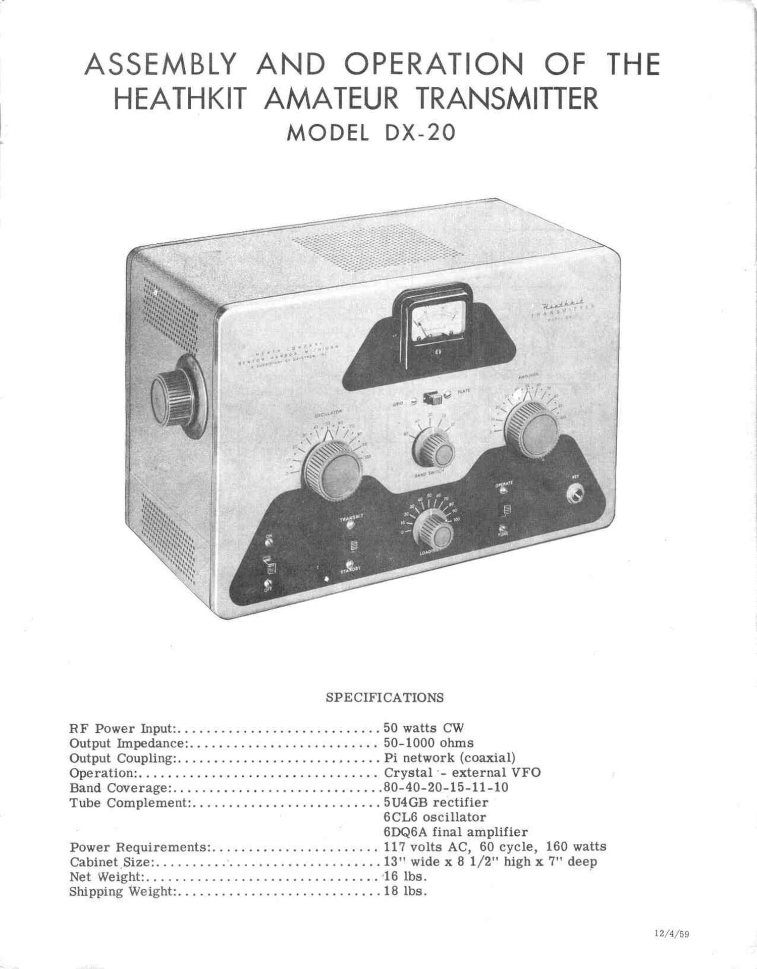
Heathkit DX 20 Assembly Manual

This is the 43 pages manual for Heathkit DX 20 Assembly Manual.
Read or download the pdf for free. If you want to contribute, please mail your pdfs to info@audioservicemanuals.com.

Page: 1 / 43
left right
Heathkit DX 20 Assembly Manual

Extracted text from Heathkit DX 20 Assembly Manual (Ocr-read)


Page 1

ASSEMBLY AND OPERATION OF THE

HEATHKIT AMATEUR TRANSMITTER
MODEL DX-20

SPECIFICATIONS
RF Power Input: ............................ 50 watts CW
Output Impedance: .......................... 50-1000 ohms
Output Coupling: ............................ Pi network (coaxial)
Operation: ................................. Crystal - external VFO
Band Coverage: ............................. 80-40-20-15-11-10
Tube Complement: .......................... 5U4GB rectifier

GCL6 oscillator
6DQ6A final amplifier

Power Requirements: ....................... 117 volts AC, 60 cycle, 160 watts
CabinetSize: ............................... 13" wide x 8 1/2" high x 7" deep
Net Weight: ................................ '16 lbs. '
Shipping Weight: ............................ 18 lbs.

12/4/59

Page 14

PARTIAL PANEL ASSEMBLY

( -) Mount a DPDT slide switch directly under the meter hole, using 6-32 x 1/4" screws. Use
a #6 lockwasher as a spacer between the switch and the panel on one side and mount the #6
solder lug between the switch and panel on the other side in the position shown in Pictorial 2
or 3.

( \) Note the position in Pictorial 2 and mount the 3-gang variable capacitor on the panel using
the three 1" flathead machine screws. See Figure 7. Insert the screw through the panel,
then through a 1/16" washer, then through a 3/4" spacer into the capacitor frame. Bend
up the three solder lugs to face horizontally toward the center of the panel.

(/) Mount the meter using the small screws, lockwashers and nuts supplied with the meter.

(, ") Put two #6 solder lugs under the nuts and washers on the meter connections. Face the lugs
toward the switch and tighten. See Pictorial 2.

3%" SPACER

(,1) Connect a .005 uf disc ceramic capac1tor 5/,go.n.rm msnen

directly across the meter solder lugs (NS)
as shown in Pictorial 3.


(,~ ) Cut a piece of blue wire 2 1/2" long. Trim
the insulation 1/4" off each end.

( ) Connect one end to the solder lug on the me- 3 W6
ter marked + (S). cmcnon

(. ) Dress the lead toward the center of the me-

ter switch and run it between the #1 and #2
terminals. Connect it to #5 (S).

(. ) Cut a piece of yellow wire 2" long and trim Figure 7
the insulation 1/4" off each end.

(2) Connect one end to the remaining meter terminal (S). Dress toward the center of the switch
and connect it to #2 (S).

(,f) Cut a piece of tinned #20 wire 3/ " long.

Slide the bare wire through switch terminal #6 and on through the grounded solder lug. Sol-
der both ends. See Pictorial 3.

(/) Cut a piece of yellow wire 8 1/2" long. Trim the insulation 1/4" off each end.
(,x) Connect one end to meter switch terminal #1 (NS). Leave the other end free.
( ) Cut a piece of blue wire 18" long. Trim the insulation 1/ 4 off each end.

( ) Connect one end to meter switch terminal #4 (NS). Leave the other end free.

(( ..) Select the 12 $2 precision resistor and trim the leads to 5/8" in length.

( ) Connect the resistor to meter switch terminals #1 (S) and #4 (S). Keep the resistor bent up
and away from the switch mounting screw and nut to avoid shorts. See Pictorial 3.

(/) Cut a piece of green wire 16" long and trim the insulation 1/4" off both ends.

Page 14

Page 21

(/) Bend the other end of the #14 wire toward the shield bracket, then up through the grounded
lug on the final amplifier tube socket (NS). See Pictorial 3.

(x ) Allow extra lead length if required either way by slipping it through the ground lug in the
center of the wire (NS). When all leads are in proper place, solder the ground at the 6DQ6A
tube socket and the ground on the tuning capacitor frame. Dress the ground lead away from

the top of the insulator.

(/0 Mount a #6 solder lug on both feed-through insulators. Face both lugs toward the rear of
the chassis and tighten between the two 6 - 32 nuts supplied with the insulators.

NOTE: For the following, Figure 13 may be used directly as a form.

II

(VET

u V4,

,L

Figure 13

Figure 14

) Cut a piece of #14 tinned copper wire 4 3/4" long.

A

(- ') Measure from one end 1 1/4" and bend the wire to a near right angle.
(r) At the 1 1/4 end of wire, bend 1/8" of the end down slightly.
( - )' At the opposite end slip a piece of insulated sleeving 3" long on up to the bend point.

)' Form another bend 1/2" in from the end, back towards itself-in a half circle. Flatten the
end slightly so it will go through the switch terminal. See Figure 14.

A

( ) Push the long hooked end of the #14 wire under the bandswitch center shaft and insert 1/8"
of the flattened end into bandswitch terminal #1 (S). See Pictorial 3.

(/) The end with the 1/8" bent end connects to the solder lug nearest the panel on the 3-gang
variable capacitor. Allow the bare wire to lie across the center lug also. Solder both con-

nections .

by ') Cut a piece .of #14 tinned wire to a length of 5". Bend 1/8" of one end down to a near right
angle.

(./) Cut a piece of insulated sleeving to 1 1/2" and slip on up to the bent end.

( ) Insert the bare lead down through the inside hole on the solder lug on IN-2 and out towards
the rear of the chassis until the 1/8" bent end comes even with the remaining end solder
terminal on the 3-gang capacitor. Push the end down in the terminal hole (S). See Picto-
rial 3.

Page 21

Page 22

,( ) Cut a piece of insulated sleeving 2 1/2" long.
(' ) Slip the insulation over the #14 wire up to 1/4" from the solder lug.

4/ ) Flatten the end 1/ " by squeezingwith pliers (see Figure 14). Align flat to pass through the
#2 terminal on the bandswitch (S).

(z) Select the 68 uuf 4 kv disc ceramic capacitor and cut both leads to 3/4". ' This capacitor
may be marked .000068 uf, 4 kv.

(" ) Maintain the capacitor tight against the chassis with one end even with the vent slot. Form
one end to fit up into bandswitch terminal #3 (NS). See Pictorial 3.

(, -) Bend the other lead around and through the remaining hole on the ground lug. When both ends
are fitted neatly in place, solder both connections.

(. -') Cut a piece of #14 tinned wire 2 7/ 8" long. Flatten 1/4" of one end slightly. See Figure
14.

( ) Insert the unflattened end through the inside hole on the solder lug on the feed-through in-
sulator IN-l below the 6DQ6A socket (NS).

( ) Form the flattened end over and connect it to the #8 terminal on the bandswitch (S). Avoid
shorting to the nut on the bandswitch.

(_. ) Select the final amplifier coil and pull the end leads out and into place. Align all leads
straight out from the coil.

( ) Shorten the longer leads to no more than 2 1/2" long.

NOTE: In mounting the amplifier coil, considerable care should be exercised to avoid breaking
the bandswitch. Do not force the leads or exert pressure on the switch terminals. It is best to
form the wires into place using small pliers and making slight bends where required to allow
leads to slip through the bandswitch terminals until all are in place. Do not clip the leads or
solder until then.

( ) Hold the coil in your left hand and use small pliers (preferably needlenose) to bend and help

insert the leads into place. Allow the two outside coil leads to go through the outside hole
in the lugs on the feed-through insulators IN-l and IN-2. See Pictorial 3.

(_ ) The first coil tap, lead #2, connects to the #4 bandswitch terminal (NS). See Pictorial 3.
(/) The next tap lead, #3, goes to the #5 terminal (NS).

( ) Coil lead #4 goes to bandswitch terminal #6 (NS).

( ) Coil lead #5 goes to bandswitch terminal #7 (NS).

( ) Work the leads through the terminals until the coil is about 1/4" in from the chassis rear.

edge, maintaining the coil position on a plane with the edge and lying down on the chassis.
(The coil is bent upward later into operating position.)

( ) Where the coil leads extend through and'beyond the bandswitch terminals, trim off the ex-
cess lead length.

( ) Twist excess lead length from the ends of the coil around the lugs on the feed-through insul-
ators (NS).

(/) Make certain all leads are properly placed and then solder all leads to the bandswitch plus
the connection on IN -1 under the 6DQ6A socket.

Page 22

Page 27

-

( ,7 Bend the #14 wire to conform with the shape in Figure
16. Use the illustration for the template.

( ) Refer to Pictorial 4. Slip the wire "U" into the two sol-
der connections on the 2-gang capacitor through the cut
slots in the lugs. The lead with the short bend goes to
the coax connector and the long bend goes through the
solder lug on the IN-l feed-through insulator.

(, *) Make certain all connections are snug in place. Avoid 6
solder drips shorting to the chassis from the 2-gang
capacitor lugs. Solder all four connections.

(/ Select the .1 at 1.2 kv paper capacitor and cut One lead Figure 16
to 1 5/8". Slip a piece of insulated sleeving 1 3/8" long
over the lead. Bend this lead sharply to a right angle
as shown in Pictorial 4.

(/) Shorten the other end of the capacitor to 1 3/4". Slip a piece of insulated sleeving 1 1/2"
long over the lead and form a right angle bend 3/8" from the end.

(/7 Consult Pictorial 4 and mount the capacitor to allow the 1 5/ 8" lead to pass 1/8" through
tie point CC2 (NS).

(1") Snug the capacitor up against the wires passing through plastic clamp A4 and allow 1/8" of
the bent end to pass through the 5U4GB rectifier pin 8 connection. Dress the capacitor
against the chassis in aligned position as in Pictorial 4 and solder pin 8.

Select the .005 at 1.6 kv large disc ceramic capacitor and cut one lead to 1" and the other
to 3/8".

(/7 Refer to Pictorial 4 and insert the 1"end through grounded tie point BB3 and on up to switch
lug #1 on the standby switch. Solder both connections.

(x ) Insert the 3/8" capacitor lead through tie point BB2 (NS).
(, ) Select the 1000 S2 1/2 watt resistor (brown-black-red) and cut both leads to 1/2".

(,/) Bend both leads to a right angle and connect one end to B82 (S). The other end connects to
switch lug #2 (S).

(/) Select the 500 $2 precision resistor and cut both leads to 1/2".

(/) Compress both leads together sufficiently to pass through tie points AA2 (S) and AA3 (NS).
Keep the resistor body away from the chassis to avoid a short.

(1,.) Select the 50 K 10-watt, wire-wound resistor and cut both leads to 1". Bend both leads to
a right angle.

(/) Compress both leads together sufficiently to pass thrdugh tie points CCl (NS) and CCZ (NS).
Position the resistor against the chassis.

(/) Cut a piece of red wire 7" long and trim the insulation 3 /8" off each end.

(/1 Slip one end through plastic clamp A2. Make a right angle bend at, and connect it to tie
point BB1 (NS).

(/) Recess the lead along with the other wires in the corner of the chassis until opposite tie point
CC2. Make a right angle bend and connect it to CC2 (S).

Page 27

Page 31

This completes the construction of your DX-ZO. "Congratulations. "

PRELIMINARY OPERATION CHECKS
Before plugging in the line cord, some precautionary checks should be exercised.

A short in the high voltage is a good point to check. This could be indicated by testing from the
6DQ6A plate cap to ground. A resistance check of approximately 30 KS2 is normal. Any resis-
tance reading very much lower than that should institute an immediate check for the cause.

Reversed filter capacitors can cause much trouble and a recheck at this point would certainly
be in order.

A shorted capacitor is possible, but not likely. However, this possibility should be looked into

with the aid of an ohmmeter. A thorough check should be made across allcapacitors associated
with the high voltage.

The entire circuit should be examined for faults in wiring or possible shorts, such as tube pin
connections touching together, wire ends shorting across where they should have been clipped
off, or resistor or capacitor leads contacting the chassis or shields. Also be sure to remove all
wire clippings and solder drops from the chassis.

If there are any short circuits, serious damage will result to the tubes or components when
power is applied.

Check all solder connections to be sure none has been missed.

For the following tune-up sequence the transmitter should be left out of its cabinet until proper
Operation is noted.

TUNING INSTR UCTIONS

The DX-20 tune up is very simple; but at the same time, unless proper procedure is exercised
poor output along with high current with consequent shortening of tube life and overheating of the
power transformer will result.

Always be sure a crystal of proper frequency is plugged in, the fact being that one at an odd fre-
quency out of the tuning range of the oscillator circuit would result in little or no drive to the

final stage. This would cause both the oscillator and the amplifier tubes to overheat and pos-
sibly damage them.

Before turning the transmitter on at a_ny time, the switch positions should be noted.

First, he sure that the (transmit-standby) switch is on (standby). The (tune-operate) switch
should be on (tune). For the following adjustments an 80 meter crystal in the range of 3500 to
4000 kilocycles would be ideal. A 40 meter 7000 to 7300 kilocycles would also suffice. Put the
(grid-plate) switch on (grid) position to read grid current or drive to the 6DQ6A final. Bear in
mind that a 40 meter crystal will not work on the 80 meter bandswitch position.

If a key is plugged in, it should be depressed or put on. (closed circuit) position. Otherwise,

with no key plugged in, the key jack provides the (closed circuit) and you may go on with the
tune-up.

It should also be noted at this time that unless the key circuit is closed, no grid current will be
indicated. Upon noting the preceeding, turn the (on-off) switch to (on). Allow about one minute

for the tubes to come up to operating temperature. There is no high voltage flowing to the tubes
until the (transmit-standby) switch is put on (transmit).

Page 31