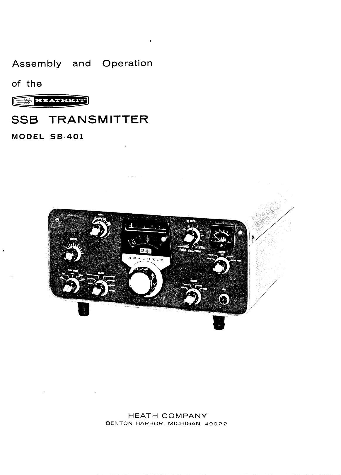
Heathkit B 401 SSB Assembly Manual

This is the 81 pages manual for Heathkit B 401 SSB Assembly Manual.
Read or download the pdf for free. If you want to contribute, please mail your pdfs to info@audioservicemanuals.com.

Page: 1 / 81
left right
Heathkit B 401 SSB Assembly Manual

Extracted text from Heathkit B 401 SSB Assembly Manual (Ocr-read)


Page 1

Assembly and Operation
of the
HEAII-IKIT

SSB TRANSMITTER
MODEL 53-401

HEATH COMPANY
BENTON HARBOR, MKCHIGAN 49022

Page 2

TABLE OF
INTRODUCTION .......................... 3
UNPACKING INSTRUCTIONS ................... 4
CIRCUIT BOARDS
Mixer-Bandpass Circuit Board
Parts List #1 ........................ 5
Step-By-Step Assembly ................. 6
Carrier Generator Circuit Board
Parts List #2 ................... .7 ...... 8
Step-By-Step Assembly ................... 10
CHASSIS PARTS MOUNTING
Parts List #3 ............................ 13
Step-By-Step Assembly
Parts Mounting-Chassis Bottom ................. 16
Coil Mounting-Chassis Top 21
Parts Mounting-Chassis Top 24
CHASSIS WIRING
Parts List #4 33
Step-By-Step Assembly
Preliminary WiringChassis Top 35
Preliminary Wiring-Chassis Bottom . , ,,,,,,, 39
Parts Mounting On Carrier Generator Shield ........ 54
Wiring Carrier Generator Shield To Chassis ........ 55
Transformer Wiring ................. 63
Preliminary Wiring-Band Switch 64
FINAL WIRING
Parts List #5 ............................ 73
Step-ByStep Assembly
Dial Assembly 75
Parts Mounting-Front Panel ............ 78
Wiring Front Panel To Chassis ........... 79
Front Panel Mounting ............... 81
Final Wiring-Chassis Top ............. 82
Final Wiring-Chassis Bottom .............. 85
INITIAL TEST ........................... 87
ALIG N ME NT
Alignment with 515-303 Receiver As A Transceiver 90
8.6 Megahertz Trap .............. 90
21 Megahertz Trap 90
Carrier Generator 90
Driver 91
8.6 Megahertz Trap Adjustment 92
Carrier Null Adjustment ........... 93
Neutralizing 94
Final Bias 94
Microphone Connection llllllllllll 95
LMO Adjustment ,,,,,,,,,,,,,, 95
Final Transmitter Adjustment 96
Alignment With SBA-4014 Crystal Accessory Kit Installed
Crystal Installation .............. 96
Equipment Required lllllll ..... 97
8.6 Megahertz Trap .............. 97
Page 2

CONTENTS

21 Megaliertz Trap ....................... 97
Heterodyne Oscillator ................... 97
Carrier Generator 97
Driver 98
8.6 Megahertz Trap Adjustment 99
Carrier Null Adjustment ............... 99
Neutralizing 99
Final Bias 100
Microphone Connection .............. 101
LMO Adjustment .................. 101
Frequency Shift Adjustment ............. 102
Final hansmitter Adjustment 102
FINAL ASSEMBLY ......................... 103
INSTALLATION AND OPERATION ................. 105
Meter Readings ................... 108
Reading Transmitter Frequency 108
Operating Conditions 109
Transmitter Operation .................. 109
Operation With SB~303 Receiver ........ . . . i 109
CW ...................... l 10
SSE ...................... l l l
Transmitter Operation Only ......... . . . . 112
CW Tune-Up ................. ll 3
$53 Tune-Up .......................... 115
IN CASE OF DIFFICULTY ..................... 117
Troubleshooting Chart .............. 113
Factory Repair Service .............. 120
SPECIFICATIONS ......................... 121
CIRCUIT DESCRIPTION
Schematic Diagram ....................... 125
Frequency Chart .............. 125
Audio Preamplifier And Cathode Follower 126
VOX Amplifier ............... I26

Relay And Anit-VOX Amplifier
Tone Oscillator And Tone Amplifier
LSB-USBCW Carrier Generator And
Cathode Follower ............
Balanced Modulator .........
Isolation Amplifier
Symmetrical Crystal Bandpass Filter
Linear Master Oscillator
LMO Mixer .............
Heterodyne Oscillator And Heterodyne-Oscillator
Amplifier
Heterodyne Mixer
Driver
Final Amplifiers
Automatic Level Control
Power Supply
Metering Circuits


CIRCUIT BOARD X-RAY VIEWS


CHASSIS PHOTOGRAPHS ...........

SCHEMATIC ..... (fold-out from Page) ..... 147

REPLACEMENT PARTS PRICE LIST 148
HEATHKIT®

Page 3

INTRODUCTION

The Heathkit Model SB-401 SSB Transmitter
is capable of SSB (upper or lower sideband) and
CW operation on all amateur bands from 3.5 to
30 megahertz. A crystal-controlled heterodyne
oscillator and apreassembled, prealigned linear
master oscillator insure highly accurate and
stable operation.

Complete Transceivc capabilities are available when the
Transmitter is used with the Healhkit Model SB-300, SB-SOl,
or 83-303 Receiver. The Transmitter can also be used with
other receivers by installing the SBA-4014 Crystal Accessory
Kit in the Transmitter. This Transmitter is compatible with
the Heathkit Model SB-200 SSB Linear Amplifier.

Other operating features include: voice oper-
ated (VOX) and push-to-talk (PTT) control in
the SSB mode; break-in keying in the CW
mode; built-in antenna change-over relay;
switched 120 VAC to operate an external an-
tenna relay; crystal filter type SSB generator;

HEATHKITQ

and automatic level control to prevent distor-
tion while providing high talk power. The large
circular dial has calibration marks every kilo-
hertz and covers 100 kilohertz for every revo-
lution to provide a bandspread equal to approxi-
mately 10 feet per megahertz. A slide-rule-
type dial pointer clearly indicates the number of
rotations of the circular dial. The knob-to-dial
ratio is approximately 4:1.

All-aluminum metal parts provide light-weight
and sturdy construction. Assembly time-saving
features include circuit boards, wiring cable
assemblies, and a preassembled LMO tuning
unit. The transformer-operated, silicon diode
power supply is a long-lite, low-heat power
source.

Refer to the "Kit Builders Guide" for complete
information on parts identification, tools, wiring,
soldering, and step-by-step assembly proced-
ures.

Page 3

Page 15

HEATHKIT

EQUIPMENT REQUIRED
The following test equipment is required for
alignment of the Transmitter.

1. A 50 5'2 nonreactive dummy load (such as
Heathkit Model HN-31 Cantenna).

2. An 11 megohm input VTVM (such as Heath-
kit Model IM-ll).

3. An RF probe for the VTVM (such as Heath-
kit Model 309-0).

4. A Ilain hand or good general coverage receiver with
calibrated S meter (such as llealhltit Model SBV303).

5. A cw key plugged into the KEY jack.
CAUTION: Do not depress the key until
specifically instructed to do so.

2 Refer to Figure 2-2 (fold-out from Page 93)
I for test point and adjustment locations.

meGAHERTz TRAP

f ( ) Preset the variable capacitor on terminal board #1 as it
is shown ianigurc 22, if it was not aligned previously
using the 88(303 Receiver.

' 21 MEGAHERTZ TRAP

The 21 MHZ trap (RFCI) was prcset at the factory. Do not
change the setting of this trap.

HETERODYNE OSCILLATOR

( ) Set the transmitter panel controls as follows:

FINAL (Knob) 80

(Lever) 50 Q

LEVEL counterclockwise
FREQ. CONTROL UNLOCKED
METER REL. PWR.
FUNCTION OFF

BAND 3.5

MODE CW

Plug the line cord into a 120 V AC wall
outlet.

Turn the FUNCTION switch to STBY.

( ) Connect the DC probe of the VTVM to the oscillator
test jack.

Page 9'7

( ) Adjust the slug of the 3.5 HET OSC coil
for a maximum indication on the VTVM
(negative DC).

CAUTION: Be sure the alignment tool is fully

seated in the coil before attempting to turn the

coil slug. It may be necessary to turn the coil
slug several turns counterclockwise to start
the oscillator.

( ) Turn the slug 1/4- turn counterclockwise to insure
positive starting of the oscillator.

( ) Turn the BAND switch from 3.5 to 7.0 and back to 3.5
to see that the oscillator starts oscillating. If it does
not, turn the slug slightly until positive operation of
the oscillator is obtained. (Readings of approximately
-3 volts or higher are normal. They will vary from
hand to band.) NOTE: When adjusting this coil in one
direction, the oscillator output voltage will change
rapidly; when adjusting the coil in the opposite
direction from the peak, the output voltage will change
slowly. Adjust the coil in the direction that gives the
slower change in output voltage.

( ) Place the BAND switch in the 7.0 position.

( ) Adjust the slug of the 7.0 HET OSC coil for
a maximum indication on the VTVM.

( ) Turn the slug 1/4 turn counterclockwise
to insure positive starting of the oscillator.

( ) Turn the BAND switch from 7.0 to 3.5
and back to 7.0 to check for positive
oscillator operation on the 7.0 band.

( ) Repeat the same procedure for the 14.0,
21.0, 28.0, 28.5, 29.0, and 29.5 positions
of the BAND switch, and adjust the cor-
responding HET OSC coil. Check each band
for proper oscillator operation by switch-
ing to a different band and back again.

( ) Return the BAND switch to the 3.5 position.

( ) Disconnect the DC probe of the VTVM from
the oscillator test jack.

CARRIER GENERATOR

( ) Set the FUNCTION switch to TRAN.

( ) Rotate the LEVEL control fully clockwise.
( ) Connect the VTVM RF probe to the E pin

on the top of the carrier generator cir-
cuit board.

( ) Depress the key. This should close both
relays.

Page 26

Page 108

METER READINGS

Refer to Figure 5-1, and study the meter scale.
Note how it reads for various positions of the
Meter switch. Observe that the meter has two
main scales and an ALC area. The scale
numbered from 0 to 10 is read directly for
relative power indications. For Grid Current
readings, each small scale division represents
.1 milliamperes. For High Voltage readings,
each small scale division represents 100 volts.

The O to 500 scale is read directly to indicate
plate current in milliamperes. The meter scales
should be interpreted as follows:

HEATHKIT

TOP EDGE OF ALC AREA REPRESENTS MAXIMUM
ALLOWABLE MODULAIION DETERMINED BY
MICROPHONE LEVEL CONTROL

RELATIVE POWER
0.!0

GRID CURRENT
0»! MA

HIGH VOLTAGE
04000 VOL 75

PLATE CURRENT
0.500 MA

FIGURE 5-1
METER SWITCH MEASURES SCALE READING RANGE OF READING
POSITION
r :4
FINAL GRID o - 1 MA
GRID o - 10 _-.10
CURRENT ' (Normal, 0-0.1)
PLATE /// FINAL PLATE 0 500 0 - 500 MA
CURRENT (Normal, 250 ma)
ALC AREA ONLY MAXIMUM MODULATION
ALc ALC VOLTAGE POINTER SET AT RIGHT EDGE or
AT 0 ALC AREA
FINAL HIGH 0 - 1000 VOLTS
HV VOLTAGE 0 ' 10 x 100 (Normal 700,800 volts)
RELATIVE ADJUSTABLE ZERO TO
REL PWR POWER 0 - 10 MAXIMUM WITH REL
OUTPUT PWR CONTROL

READING TRANSMITTER FREQUENCY

To read the desired frequency, add the BAND
switch setting in egahertz, to the slide rule
pointer setting in undreds of kilohertz and the
circular dial setting in kilohertz.

For Example: If the BAND switch is set to 3.5,
the slide rule pointer is betweenZ and 3, and the

circular dial is set to 53, the frequency is
3.753 MHz. If the BAND switch is set to 14.0,
the slide rule pointer between 0 and 1, and the
circular dial is set to 12, the frequency is
14.012 MHz,

Figure 1-2 (fold-out from Page 86) explains
each front panel control.

Page 32

Page 114 -HEAII-IKIT

Tuneup the Transmitter as follows:

SWITCH OR SWITCH OR COMMENTS
C ONTROL C ONTROL
POSITION
=
A. FUNCTION TRAN or TRCV

Adjust LEVEL control for approximately .5 ma (midscale)

B. M DE
0 TUNE with METER switch in GRID position;

Turn the METER switch to REL PWR and adjust for

maximum meter indication (plate current will be

approximately 220 ma).

D DRIVER Adjust for maximum relative power meter read-
' ing. Then turn METER switch to PLATE. (1p

should be about 220 ma.)

C. FINAL tune

E- Egg? Set METER switch to REL PWR and adjust for a half-scale
reading when fully loaded on the 3.5 band.

F. MODE CW

G, LEVEL Key the Transmitter and quickly adjust the LEVEL control
m to the point where meter reading ceases to increase.

H. FINAL LOAD Adjust for maximum meter reading.

I. Repeat steps C, D, and H.

J. Key open.

K. METER GRID Close the key and adjust the LEVEL control for a meter
reading of appronmately .5 ma.

L. LEVEL Key the Transmitter and adjust for approximately 0.5 ma

meter reading.

For final adjustment of the Relative Power con-
trol, refer to Figure 1-2 (fold-out from Page 86).

The Transmitter is now properly loaded for
maximum CW performance at the chosen oper-

ating frequency.

For Single Sideband operation, change the MODE
switch to either USB or LSB, and adjust the
LEVEL control. Use the following chart for the
initial setup for SSB operation.

Page 41

/
/

-HEATHKIT

Page 123

Tube Complement. . . . .

Diode Complement. . .

account's-ouc-

Power Supply. . . . . . .

nun-unnuouuoao

Power Requirements. . .

Cabinet Dimensions. . . .

Net Weight. . . . . .

Equipment Used To Prepare Specifications. . . .

1 - 0A2: Regulator.

1 - 6AU6: Isolation Amplifier.

1 - 6AV11: USE, CW, and LSB Carrier Gener-
ator, and Carrier Generator Cathode Fol-
lower.

1 - 6AW8: Heterodyne Oscillator and Receiver
Heterodyne Oscillator Amplifier.

1 - 6CL6: Driver.

1 - 6D10: VOX, Relay, andSide Tone Amplifier.

1 - GEAB: Audio Preamplifier and Cathode Fol-
lower.

2 - 6EW6: LMO Mixer, Heterodyne Mixer.

1 - 6J11: Anti-VOX Amplifier and Tone Oscil-
later.

2 - 6146: Final Amplifiers.

1 - 6BZ6: LMO.

5 - Crystal Diodes: Balanced Modulator and
Relative power metering.

12- Silicon Diodes: Power Supply, VOX Recti-

fiers, ALC Rectifiers, and DC Blocking.

Transformer operated.

105-125 or 210-250 volts AC, 50/60 Hz.
Standby: 80 watts.
CW: 260 watts (key down).

14-7/8" Wide x 6-5/8" high x 13-3/8" deep.

26-1/2 lbs.

Heath lG-72 Audio Generator.
Heath IM-ll VTVM with 309-0 RF Probe.
Heath IM-Zl AC VTVM.
Heath PIN-31 "Cantenna."
Panoramic Radio Products, Inc.
"Panalyzor," Model SB-12A.
Measurements Corporation, Standard Signal
Generator, Model 80.
Hewlett Packard Electronic Counter,
Model 5248.
Boonton RF Voltmeter, Model 91 -C and 91-CA.
Bird Thruline Wattmeter, Model 43.

The Heath Company reserves the right to discon-
tinue instruments .and to change specifications at
any time without incurring any obligation to'

-:

incorporate new features in instruments pre-
viously sold.