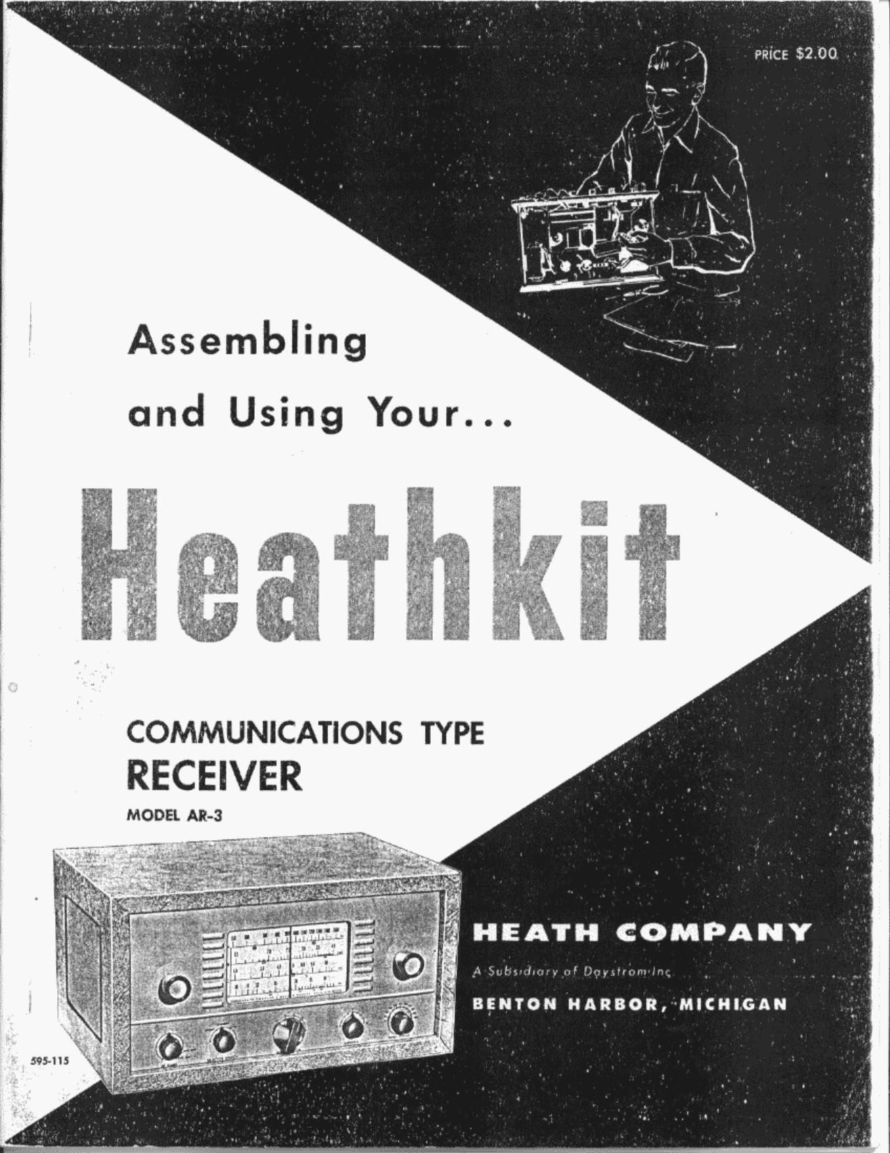
Heathkit AR 3 Schematic

This is the 14 pages manual for Heathkit AR 3 Schematic.
Read or download the pdf for free. If you want to contribute, please mail your pdfs to info@audioservicemanuals.com.

Page: 1 / 14
left right
Heathkit AR 3 Schematic

Extracted text from Heathkit AR 3 Schematic (Ocr-read)


Page 1

Assembling

and Using Your. . .

COMMUNICATIONS TYPE
RECEIVER

MODEL All-3

HEATH COMPANY

A Sufvlnw'. .M 1>«;..u.(.mn;

BENTON HARBOR, 'MICHI.GAN

595-115

Page 2

ASSEMBLY AND OPERATION OF THE

HEATHKIT COMMUNICATIONS TYPE RECEIVER
MODEL AR-3

SPECIFICATIONS
Frequency Range: ........................... 550 kc to 30 mc in four bands
Tube Complement: .......................... 1 - IZBES oscillator and mixer

l - IZBA6 IF amplifier

1 - 12AV6 second detector, AVC, first audio am-
plifier, reflex BFO and noise limiter

l - IZVGGT beam power output

1 - 5Y3 full wave rectifier

Power Requirements: ....................... 105-125 volts AC 50-60 cycles 40 watts
Dimensions: ............................... 11 1/2" wide x 5 3/4" high x 6 3/4" deep
Shipping Weight: ............................ 12 lbs.
Civil Defense frequencies and Amateur bands plainly marked on dial.
CONTROLS
General Coverage Tuning Band Switch
Band Spread Tuning Noise Limiter On/Off
Phone-Standby-CW Switch RF Gain Control/AVG On/Off
Headphone Jack AC On/Off - Audio Gain
Antenna Trimmer Accessory Socket

Sockets for connecting Heathkit model QF-l Q Multiplier on rear of chassis.

Page 6

( ) Connect the other uninsulated wire to W (NS).

( ) Connect a wire from VV (S) to R3 (S).

( ) Connect a wire from R2 (S) to the remaining voice coil terminal on the speaker (S).
( ) Connect the blue lead from the output transformer to A3 (S).

( ) Connect the red lead to B I (S).

( ) Turn the receiver over and connect the center lead in the Spirashield coming through the
hole beneath the volume control VC to WW (NS).

( ) Connect an .02 ufd ceramic capacitor between WW (S) and VC2 (S) (use sleeving).

( ) Readjust the dial drum pulley so that the opening in the outer rim is straight up when the
tuning condenser is fully meshed. The spacing between the drum and the rear of the dial
plate should be approximately 1/8". Tighten the set screw permanently.

( ) String the dialcord as shown. It has been pre-cut to the proper length and no further ad-
justment is necessary. See Figure 14.

( ) Mount one of the large black and chrome knobs on the shaft of the volume control VC and
s tighten.

( ) Mount the other large knob on the main tuning capacitor shaft.

( ) Mount the small black knob without a pointer on the shaft of the bandspread capacitor and
tighten.

( ) Mount the large black knob with the white line on the bandswitch shaft. Position the knob
so that the line points correctly at each of the switch positions.

Page 21

Page 8

Set the ANTENNA TRIMMER to about 50% meshed. Set the generator to 30 me and adjust the
band "D" oscillator trimmer for maximum meter deflection. The oscillator trimmer for this
band is located at the base of the rear section of the tuning condenser. The adjustment will be
critical and the meter indication may change when the tool is removed from the screw head.

Maximum reading should be present after the tool is removed. There will always be a residual
reading due to the presence of a constant AVC voltage.

Adjust the band "D" antenna trimmer until maximum meter indication occurs exactly at 30 me
on the dial plate. This trimmer is located at the base of the front section of the tuning conden-

ser.

Check the image frequency by setting the generator t030.910 me, which is twice the IF frequency
above 30 me. If the image appears at 910 kc below 30 inc rather than above, then it will be nec-
essary to unscrew the band "D" oscillator trimmer until these two maximum points are properly
positioned. They should occur at 30 mc and again at 30.910 mc.

Turn the bandswitch to band "C" and tune the receiver to 4 me. Set the signal generator to 4
me and adjust the band "C" oscillator coil slug for maximum indication on the meter. Now ad-
just the band "C" antenna coil clug for maximum indication on the meter.

Turn the generator to 10 mc and tune the receiver to the same frequency. Adjust the band C"
oscillator trimmer capacitor for maximum indication on the meter. Return the receiver and
generator to 4 mc and touch up the band "C" oscillator coil slug again for maximum indication.

Turn the bandswitch to band "B" and tune the receiver to 1.5 mc. Tune the generator to the
same frequency. Adjust the band "B" oscillator coil slug for maximum indication on the meter.
Also adjust the band "B" antenna coil slug for maximum indication. Tune both the receiver and
generator to 4 mc. Adjust the band "B" oscillator trimmer for maximum indication. Repeat
the adjustment of the oscillator coil slug again at 1.5 mc.

Turn the bandswitch to band "A"and tune the receiver and generator to .55 me (550 kilocycles).
Adjust the band "A" oscillator coil slug for maximum indication on the meter. Now adjust the
band "A" antenna coil slug for maximum indication. Tune both the receiver and generator to
1.5 inc (1500 kilocycles) and adjust the band "A" oscillator trimmer for maximum indication.
Repeat the.oscillator coil slug adjustment at 550 kilocycles.

When tuning the receiver, the image will always fall below the signal frequency. This completes
the alignment of your Heathkit model AR-3 Receiver.
BFO ADJUSTMENT

Turn the PHONE-STANDBY-CW switch to the CW position. Reduce RF gain and advance volume.
Tune in a steady carrier signal on any band and adjust the BFO coil slug. A point will be found
where a high-pitched whistle is heard, gradually descending in pitch until a point of no signal is
reached (called "zero-beat") after which the signal will again appear and increase in pitch until
it disappears. On either side of the zero-beat point just described, will be found a point where
the pitch of the signal is most pleasing to the ear. This is the point to which the BFO coil slug
should be adjusted. When using the receiver for CW reception, always tune for the same pitch
signal, since this centers the incoming signal in the IF passband.

The signal generator, supplying an unmodulated signal may be used in adjusting the BFO and in
many cases, it will be simpler to do so, since the effect of fading will be eliminated.
IN CASE OF DIFFICULTY
1. Recheck the wiring. Trace each lead in colored pencil on the pictorial as it is followed in
the receiver. Most cases of difficulty result from wrong connections. (Often having a
friend check the wiring will reveal a mistake consistently overlooked. )

Page 23