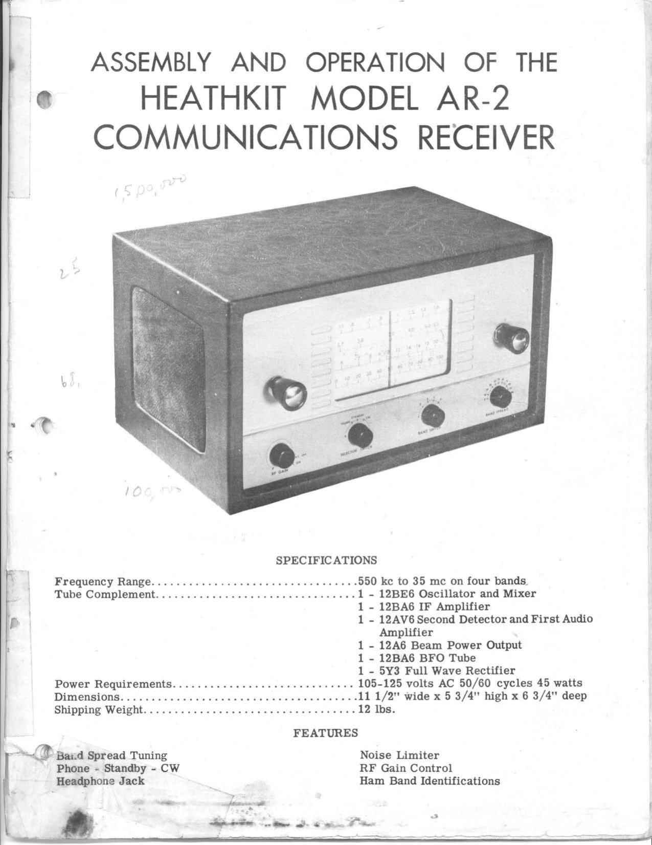
Heathkit AR 2 Schematic

This is the 15 pages manual for Heathkit AR 2 Schematic.
Read or download the pdf for free. If you want to contribute, please mail your pdfs to info@audioservicemanuals.com.

Page: 1 / 15
left right
Heathkit AR 2 Schematic

Extracted text from Heathkit AR 2 Schematic (Ocr-read)


Page 1

p ASSEMBLY AND OPERATION OF THE
3 HEATHKIT MODEL AR-2
COMMUNICATIONS RECEIVER

SPECIFICATIONS
Frequency Range ................................. 550 kc to 35 me on four bands.
, Tube Complement ................................ l - 12BE6 Oscillator and Mixer
1 - 12BA6 IF Amplifier
f 1 - 12AV6 Second Detector and First Audio
Amplifier

1 - 12A6 Beam Power Output
1 - IZBAS BFO Tube
1 - 5Y3 Full Wave Rectifier

Power Requirements ............................. 105-125 volts AC 50/60 cycles 45 watts
Dimensions ...................................... 11 1/2" Wide x 5 3/4" high x 6 3/4" deep
Shipping Weight .................................. 12 lbs.
FEATURES
f"~@ Band Spread Tuning Noise Limiter
Phone - Standby - CW RF Gain Control
Headphone Jack Ham Band Identifications

«C- J- o «a. 3»

Page 2

INTRODUCTION

The Heathkit model AR-Z Communications Receiver is designed to provide all of the features
normally expected in a receiver of this type. Simplicity and ease of construction has been ac-
complished through the use of highly efficient, straightforward circuitry and a very practical
chassis layout. All components have been selected carefully for quality and durability.

Four frequency bands, in conjunction with direct planetary drive, provide continuous tuningfrom
550 kc to 35 me. No communication type receiver would be complete without band spread, and
model AR-2 has been equipped with a type that operates at optimum efficiency on all frequenCy
ranges. The logging scale will be particularly helpful in amateur work at the higher frequencies .

For CW reception, a complete BFO circuit may be switched into operation by means of the sel-
ector switch. When operating on CW, it is desirable to tie-activate the normal AVC circuit and
control the sensitivity manually. Both functions are accomplished by the RF gain control. The
stand-by position of the selector switch allows operating temperatures to be maintained so that
the operator may select instantly the type of reception desired at any one particular time.

The noise limiter switch at the rear of the chassis is used to minimize the interference caused
by sharp transient pulses. This type of interference is occasionally encountered in highly sen-
sitive receivers such as the model AR-Z. The kit is complete with a transformer operated pow-
er supply, shielded coil assembly, and a 5 1/2" PM dynamic loudspeaker. Modernistic styling
and the easily read dial assembly will contribute greatly to the receiver's attractiveness and
efficiency.

CIRCUIT DESCRIPTION

An external antenna is connected to the antenna terminal at the rear of the chassis. The ground
terminal, which is nearest the right rear corner of the chassis, should be securely fastened to
a good solid ground point. A cold water pipe is excellent for this purpose.

The signal is applied through the antenna coil of the selected frequency band to the control grid
of a lZBEG tube, used as a combination oscillator and mixer. A 100 $2 suppressor resistor is
used in series with the grid to insure maximum stability. The antenna and oscillator sections of
this tube are tuned simultaneously by means of the dual tuning condenser and added band spread
capacity. The oscillator signal is coupled to the oscillator grid of the same tube and thus, the
heterodyne action takes place. A 455 kc signal is the result of this mixing and it is amplitude
modulated by the audio portion of the RF signal. This intermediate frequency is amplified by
the IF amplifier, 12BA6. Coupling before and after the IF stage is accomplished with the high
gain miniature type IF transformers. Most of the sensitivity and selectivity of the receiver is
developed in this section. One position of the switch in the cathode circuit of this tube allows
normal operation with 150 Q as the cathode resistance. The other position shorts AVC to ground
and makes the cathode resistance variable. This constitutes the RF gain control.

After IF amplification, the signal is coupled to one of the diode plates of the second detector ,
12AV6. The positive signal peaks cause the diode to conduct, charge the diode filter condenser ,
and develop a filtered voltage across the volume control. AVC voltage is present at the negative
side of the control and is coupled through a filter network to both the mixer and IF stages. Cou-
pling is made from the volume control through a .05 ufd condenser to the control grid of the tri-
ode section of the 12AV6 ibe. This section acts as the first audio amplifier.

From the p12: - of the 12AV6, the audio signal is applied through a .02 pfd condenser to the con-
trol grid of a beam power pentode, 12A6. After power amplification, the signal is matched to the
speaker voice coil through the output transformer. The tone quality is further improved by us-
ing a .005 ufd condenser across the primary winding of the transformer. A 10 S2 resistor pro-
vides proper matching when headphones are used and it causes only a very slight mis-match
when the speaker is used. However, if no attempt to use headphones will ever be made, the 10
S2 resistor may be eliminated in order to gain approximately 2db with the speaker. Headphones
should never be used without the resistor because the secondary winding of the output trans-

Page 3

Page 3

former will be practically unloaded and it could result in a great deal of damage. The closed
circuit jack opens up the speaker voice coil circuit when headphones are plugged in, and there-
fore, there is no need for a separate speaker switch.

Referring back to the 12AV6 tube, there is a connection between the other diode plate and the
control grid of the 12A6, through a SPST slide switch. This is the noise limiter circuit. With
the switch closed, the diode plate is charged to the average amplitude of the audio signal present
at the grid of the output tube. If a sharp noise pulse occurs, the positive peaks will be elim-
inated by the rectification action of the diode. Atmospheric and other similar types of interfer-
ence will, therefore, be greatly subdued.

When the signal input to the receiver is merely CW, no detection can take place in the second
detector because there are no amplitude variations. Therefore, the signal at the first diode
plate of the detector is 455 kc interrupted only by the keying of the distant transmitter. Another
signal becomes necessary under these conditions in order that the difference between it and 455
kc may be audible. This signal is provided by the BFO circuit consisting of a BFO coil and a
IZBA6 tube wired as a triode, along with appropriate resistors and condensers. The circuit is
activated by the selector switch, which closes the cathode circuit of the BFO tube. Coupling is
accomplished through the stray capacity of the circuit to the first diode plate of the 12AV6 tube .

In the standby position of the selector switch, the BFO circuit is open in addition to the ground
return circuit of the complete receiver. In the phone position, the ground circuit is completed
while the BFO remains open. Tube filaments are activated at all times to provide instantaneous
operation of any circuit when the switch is manipulated.

NOTES ON ASSEMBLY AND WIRING

The Heathkit model AR-Z Communications Receiver, when constructed in accordance with the
instructions in this manual, is a high-quality unit capable of many years of trouble-free service .
We therefore urge you to take the necessary time to assemble and wire the kit carefully. Do
not hurry the work, and you will be rewarded with a greater sense of confidence, both in your
receiver and your own ability.

This manual is supplied to assist you in every way to complete the kit with the least possible
chance for error. We suggest that you take a few minutes now and read the entire manual
through before any work is started. This will enable you to proceed with the work much faster
when construction is started. The large fold-in pictorials are handy to attach to the wall above
your work space. Their use will greatly simplify the completion of the kit. These diagrams
are repeated in smaller form within the manual. We suggest that you retain the manual in your
files for future reference, both in the use of the receiver and for its maintenance.

UNPACK THE KIT CAREFULLY AND CHECK EACH PART AGAINST THE PARTS LIST. In
so doing, you will become acquainted with each part. Refer to the charts and other information
shown on the inside covers of the manual to help you identify any parts about which there may
be a question. If some shortage is found in checking the parts, please notify us promptly and
return the inspection slip with your letter to us. Hardware items are counted by weight, and if
a few are missing, please obtain them locally if at all possible.

Read the note on soldering on the inside of the back cover. Crimp all leads tightly to the ter-
minal before soldering. Be sure both the lead and the terminal are clean of wax, corrosion, or
other foreign substances. Use only the best rosin core solder, preferably a type containing the
new activated fluxes such as Kester "Resin-Five, " Ersin "Multicore, " or similar types.

NOTE: ALL GUARANTEES ARE VOIDED AND WE WILL NOT REPAIR OR SERVICE
INSTRUMENTS IN WHICH ACID CORE SOLDER OR PASTE FLUXES HAVE BEEN
USED. WHEN IN DOUBT ABOUT SOLDER, IT IS RECOMMENDED THAT A NEW
ROLL PLAINLY MARKED ."ROSIN CORE RADIO SOLDER" BE PURCHASED.

Page 4

Page 5

( KReadjust the dial drum pulley so that the opening in the outer rim is straight up when the
tuning condenser is fully meshed. The spacing between the drum and the rear of the dial
plate should be approximately 1/8". Tighten the set screw permanently.

(~/) String the dial cord as shown. It has been pre-cut to the proper length and no further ad-
justment is necessary.


ll . _ V
H but mm H

um,r /

uswrfn_ I


um .
mu 1


nut vim

Figure 13

(i. ) With the tuning condenser fully meshed, make a distinguishable mark on the dial cord di-
rectly above the extreme left edge of the scale. Rotate the tuning condenser fully clockwise
and note the position of the mark with respect to the right edge of the scale. Change the
position of the mark until the width of the scale is exactly centered in the width of the move-
ment of the mark from one extreme position to the other. Install the dial pointer as shown,
with its center fastener resting on the mark made on the dial cord. Be careful when crimp-
ing the fasteners because they will cut the dial cord if they are too tight. Exert just enough
pressure so that the pointer is perpendicular to the edge of the dial plate and moves with
the dial cord.

(\/) Install the two larger knobs on the shafts of the tuning condenser and the volume control.
The three small pointer knobs are for the RF gain control, stand-by switch and the band
switch. The remaining knob is to be installed on the shaft of the band spread condenser .

NOTE: The large bushing with the plastic washer is to be used after the receiver has been in-
stalled in a cabinet or panel of your choice and the control plate mounted over the control shafts .
The bushing end is slipped over the band spread condenser shaft, through the control plate, and
tightened down by means of the set screw. The hair line should coincide with the zero mark on
the plate with the band spread condenser fully meshed. For alignment purposes however, the
control plate is not required.

You are now ready to test and align the receiver. If a standard VTVM, a 20 K9 per volt multi-
meter, or any sensitive DC measuring device is available, it is recommended that you proceed
with the alignment of the set without the loudspeaker. If however, such instruments are not
obtainable, you may permanently mount the speaker according to instructions on Page 23, and
align the set by ear. In any case, a signal generator is required and the electronic method is

preferable.
PRELIMINARY TEST

1. Adjust the tuning core in band "A" oscillator coil until the screw protrudes from the clip
about 3/8".

2. , Adjust each of theS trimmers about half way. The IF transformers are factory adjusted to
their approximately correct positions.

Page 20