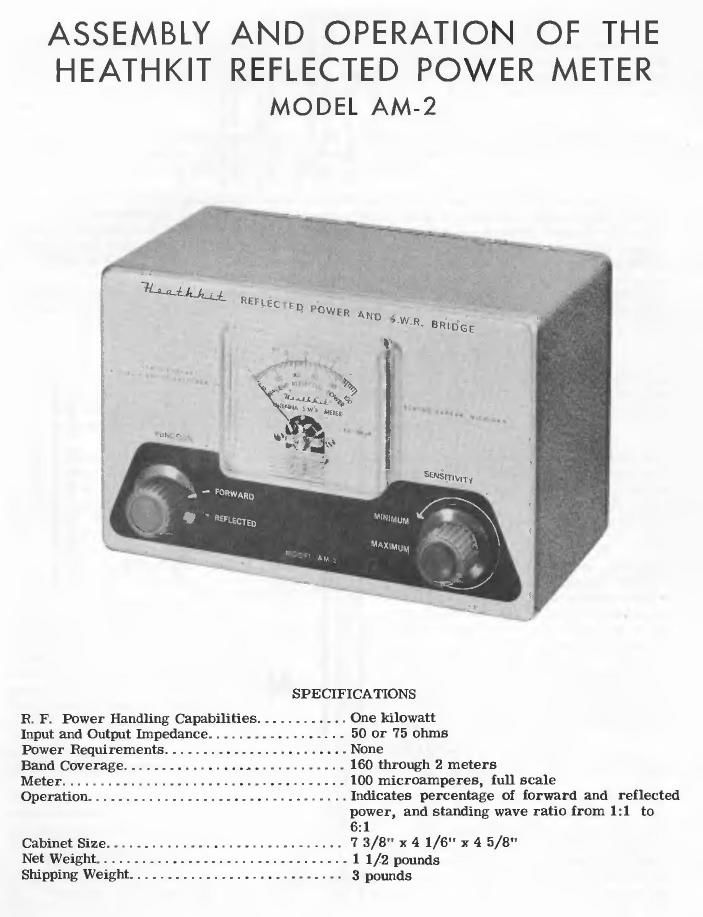
Heathkit AM 2 Schematic

This is the 4 pages manual for Heathkit AM 2 Schematic.
Read or download the pdf for free. If you want to contribute, please mail your pdfs to info@audioservicemanuals.com.

Page: 1 / 4
left right
Heathkit AM 2 Schematic

Extracted text from Heathkit AM 2 Schematic (Ocr-read)


Page 1

ASSEMBLY AND OPERATION OF THE

HEATHKIT REFLECTED POWER METER
MODEL AM-2

SPECIFICATIONS

. . One kilowatt
. . 50 or 75 ohms
. . None

Input and Output Impedance. . . .
Power Requirements .......

Band Coverage. . . . 160 through 2 meters

Meter .... . . 100 microamperes. mu scale

Operation. Indicates percentage of forward and reflected
polwer, and standing wave ratio from 1:1 to

CabinetSize.... i. 73/8" x41/6" x45/8"

Net Weight. . .. 1 1/2 pounds

ShipPing Weig - -- 3 pounds

Page 2

INTRODUCTION

Primarily, the Heathlo't Model AM-Z Reflected Power and S. W. R, Bridge has been made avail-
able to provide the Radio Amateur, or operatorof similar transmitting equipment, witha reliable
but inexpensive means of determiningwhether the radio (requencypower output ofwhichhis trans»
mitter is capable is being transferred to the radiating portionof his antenna system with the best
practicable efficiency.

The AMeZ will also be found useful, Within its specification limits, in any application which
requires the measurement or continuous monitoring of reflected power or S. W. R. (standing wave
ratio) in a coaxial line of 50 or '70 ohm nominal impedance,

Since the power handling capability of the Heathkit AM-2 is in excess of the legal limit of radio
frequency power output for amateur radio transmitters, and since its insertionloss is negligible,
it can be permanently installed in the coaxial transmission line of anyamateur transmitter instal-
lation, at the operating position; this will permit continuous monitoring oi transmitter tuning,
transmission line to antenna impedance match at the operating frequency, and relative power
output. Even though it is Installed in this manner, the AM-Z is still conveniently available {or
occasional or Irequent use in connection with the design and construction of coupling networks,
antenna systems, etc. , since it is small in size, requires no external power source, and employs
standard VHF coaxial connectors.

CIRCUIT DESCRIPTION AND OPERATING PRINCIPLES

The circuit of the Heathkit Model AM~2 Reflected Power and S. W, R. Bridge is based upon that
of a device developed at the U. S. Naval Research laboratory, Washington, D C. and described
by NorGurden in N. R. L. report No. 3538, titled "A Relleclometer {or H-F Band. " Simplified
versions have also been described in various amateur radio publications.

In the broadest terms, the AM-2 consists of a short section of transmission line to which two
small linear inductors are coupled both inductively and capacitivelyi The radio frequency cur-
rent flowing in each inductor and its load resistor is rectified by agermanlum diode and filtered
by a ceramic capacitor, The "Function switch selects the direct current Output of either diode
and applies it to a variable sensitivity metering circuit consisting 01 a linear potentiometer and
a 0-100 microammeter.

The circuit configuration as shown on Page 2, actually constitutes two radio frequency bridges,
the "null indicator" being switched from one bridge to another. We will reier to the two bridges
as the "Reflected" bridge and the "Forward" bridge, using the "Function" switch terminology.
The proportion of capacitive and Inductive coupling between the transmission line and the linear
inductors or probes is such that the reflected" bridge will be balanced (or the condition of no
reflected power (perfect [incite-load impedance match); the meterwill thereiore indicate a stand-
lng wave ratio (5. W R.) oi unity and zero percent reflected power for this condition, when the
svntch is in the "Reflected" position, I! the impedance of the line termination (antenna) at the
operating frequency differs from thal o! the line (50 or 70 ohms), some power will be reflected
back from the antenna and the bridge will be unbalanced. The meter will indicate the degree of
unbalance in terms of its scale calibrations of "Percent Reflected Power" and approximate
"S. W. R.". For example, If the transmission line is either "shorted" or "open" at the load
(antenna) end, essentially all of the power will be reflected, and the meter will indicate approx-
imately 100% reflected power, representing an infinitely large 5, w. n.

When the "Function" switch is in the "Forward" position, the meter will indicate "iorward"
bridge balance (zero) only when there is no radio frequency current flowing in the forward dir-
ection (toward the transmission line load). Asfomard current is increased from zero upward,
the bridge becomes unbalanced, and the meter swings up-scale. The actual meter indication
will depend upon (1), the amount of current flowing toward the antenna in the transmission line,
and (2), the setting of the limit "Sensitivity" control. Therelore the AM.2 constitutes, when
the "Function" switch is in the "Forward" position, a reliable transmitter tuning indicator, in
addition to serving as a continuous monitor of transmitter output. It should be noted that the