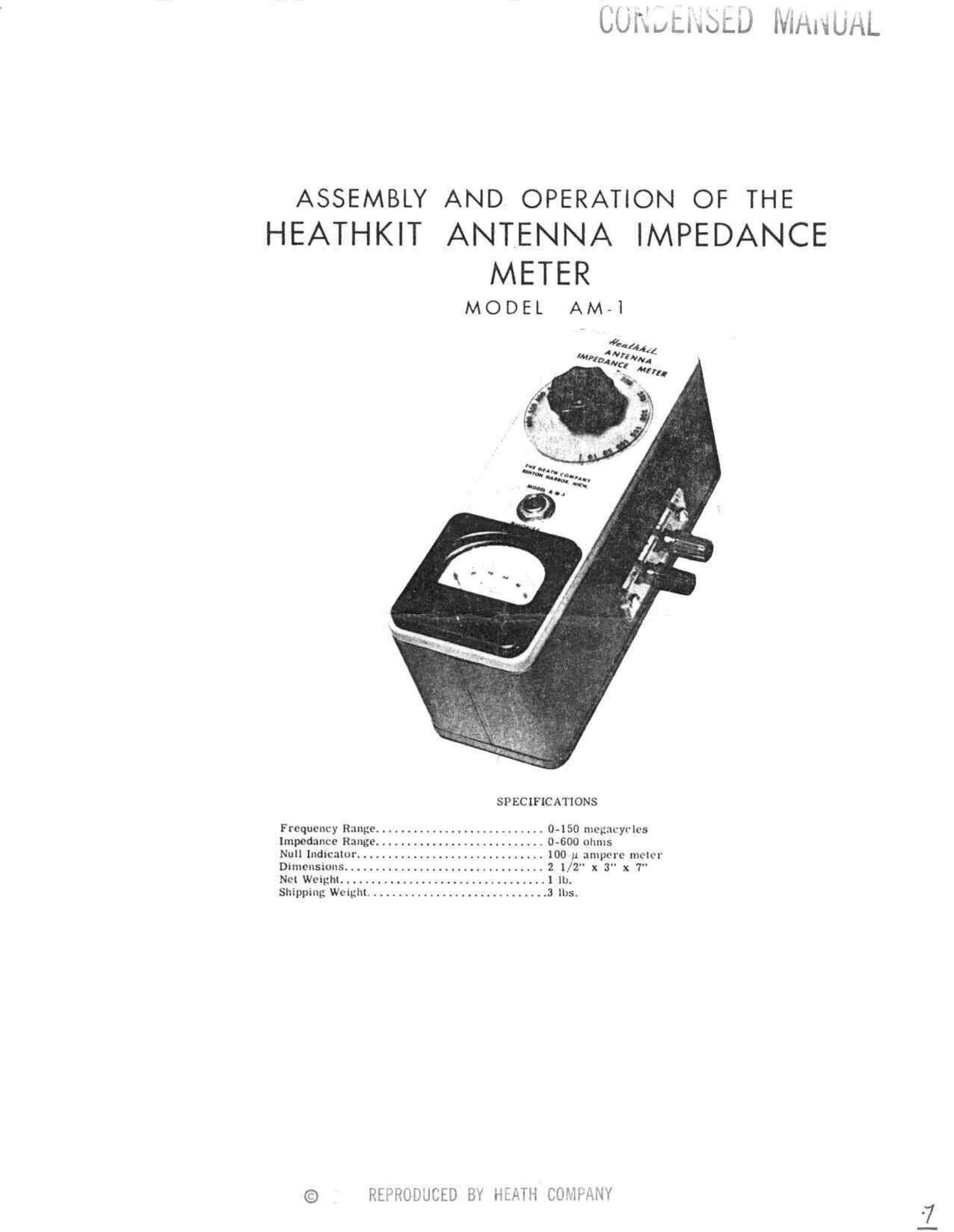
Heathkit AM 1 Schematic

This is the 10 pages manual for Heathkit AM 1 Schematic.
Read or download the pdf for free. If you want to contribute, please mail your pdfs to info@audioservicemanuals.com.

Page: 1 / 10
left right
Heathkit AM 1 Schematic

Extracted text from Heathkit AM 1 Schematic (Ocr-read)


Page 2

200 A

.005 CK 705
INPUT

ANTENNA IMPEDANCE METER SCHEMATIC

Page 10

PARTS LIST

PART PARTS DESCRIPTION PART PARTS DESCRXPTION
N0. Per Kit No. Per Kit
Resistors-Condensers- Rectifiers Hardware
1-20 1 10 K9 resistor 250-8 2 #6 x 3/8 sheet metal screw
2-83 2 200 Q resistor 1% 250-10 6 6-32 x 1/2 screw
10-34 1 800 Q potentiometer 250-16 1 8-32 x 3/16 set screw
21-27 2 .005 Md ceramic condenser 252-3 10 6-32 nut
56-4 1 Crystal rectilier 252-7 2 Control nut
253-10 2 Control nickel washer
Meters-Knobs-Insulatora 254-1 6 #6 lockwashex
75-6 2 Polystyrene insulator 255-2 2 66 x 3/18 spacer
75-14 1 Polystyrene mounting plate 259-! 5 06 solder lug
loo-M168 2 Binding post cap, hlack 259-6 2 Solder lug, small
too-M161? 2 Binding poet cap, red
loo-M39 l Dial Miscellaneous
407-24 1 100 uA meter 261-1 4 Rubber feet
453-? 1 Insulated shaft extension 340-2 1 length Bare wire
436-1 1 Jack
Sheet Metal Parts 427-2 4 Binding post base
90-28 1 Cabinet 595-79 1 Manual
203-52F65 1 Panel
204-M60 l Bracket iront
204 -M61 1 Bracket back

Page 18