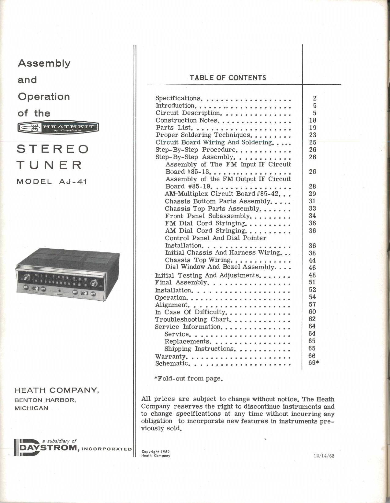
Heathkit AJ 41 Schematic

This is the 41 pages manual for Heathkit AJ 41 Schematic.
Read or download the pdf for free. If you want to contribute, please mail your pdfs to info@audioservicemanuals.com.

Page: 1 / 41
left right
Heathkit AJ 41 Schematic

Extracted text from Heathkit AJ 41 Schematic (Ocr-read)


Page 1

Assembly

and

Operation

STEREO
TUNER

MODEL Ad-4I

HEATH COMPANY,

BENTON HARBOR,
MICHIGAN

a subs/diary of

II
DAYSTROM, INCORPORATED
Ed

TABLE OF CONTENTS

SpecificationS.
Introduction.....................
Circuit Description. . . . . . . . .......
Construction Notes . . . . ..... . . . .
Parts List. . . . . . . . ............
Proper Soldering Techniques .........
Circuit Board Wiring And Soldering. . . . .
Step- By- Step Procedure. . . . . . ..... .
Step- By- Step Assembly. . . . . . . .
Assembly of The FM Input IF Circuit
Board#85- 18. . . . . . .
Assembly of the FM Output IF Circuit
Board#85- 19. .....
AM-Multiplex Circuit Board #85-42. . .
Chassis Bottom Parts Assembly. . . . .
Chassis Top Parts Assembly. . .....
Front Panel Subassembly. . . . . . . . .
FM Dial Cord Stringing. . . . . . . . . .
AM Dial Cord Stringing. . . . . . . . . .
Control Panel And Dial Pointer
Installation. . . .
Initial Chassis And Harness Wiring. . .
Chassis Top Wiring. . . . . . . . . . . . .
Dial Window And Bezel Assembly. . . .
Initial Testing And Adjustments ..... . .
Final Assembly. . .
Installation. . . . .....
Operation...... ...........
Alignment. . .
In Case Of Difficulty ........ . .....
Troubleshooting Chart. . . ..... . . . . .
Service Information ......... . . . . . .
Service. .
Replacements,
Shipping Instructions. . . . . . . . . . . .
Warranty............ .....
Schematic... .....

*Fold- out from page.

18
19
23
25
26
26

26

All prices are subject to change without notice. The Heath
Company reserves the right to discontinue instruments and
to change specifications at any time without incurring any
obligation to incorporate new features in instruments pre-

viously sold,

Copyright 1962
Heath Company

12/14/62

Page 2

Page 2

_HE.-‚¬+EH3§Tr
SPECIFICATIONS

FM SE C TION

TuningRange........................

Intermediate Frequency (IF). . . . . . . . . . .

Antenna

Output Impedance (Cathode Follower). . . . . . . .

OutputVoltage.......................

QuietmgSensitivity....................

Audio Frequency Response. . . . . . . . . . . . . . .

Maximum Deviation Sensitivity.. . . . . . . . . . .

Deviation Sensitivity. . . . . . .. . . . . . . . . . . .

HarmonicDistortion...................

Intermodulation Distortion. . . . . . . . . . . . . . .

88 to 108 megacycles.
10.7 megacycles.

300 S2 balanced.
Variable to 4000 9.

Nominal .5 volt with 3 uv, 30% modulation in.

+20
Output Voltage t1 db from 3 [iv to 100,000 nv in
'5 v Signal om
+IO
0
DB
20 db 0! quieting
-IO
-2 0
DEVIATION-22.5 KC
Tuning-93 MC
Modulation-400 cps 40 db Hum and Noise
-3 0
-4O
2 5 I 2 3 4 5 IO 20 30 4050 IOO

Microvolts in ,
QUIETING SENSITIVITY

2 uv for 20 db of quieting.
3 [iv for 30 db of quieting.
20 uv for full quieting, 40 db.

i2 db from 20 to 20,000 cps.
5 NV, 400 cps, 100% modulation in. (Minimum
signal with 100% modulation that will pass through

the tuner without exceeding rated distortion).

20 kc (1100 uv in). (Minimum deviation re-
quired to produce rated output).

Less than 1% (1100 uv, 400 cps, 100% modula-
tion).

Less than 1%.

HEATER]: T
a Dug/114,»:

Page 3

ImageRatiO.........................
Capture Ratio.......................
AFC CorrectionFactor. . . . . .. . . . . . . . . . .
Amplitude Modulation Suppression. . . . . . . . .
Hum AndNoise......................
FM STEREO CONVERTER SECTION

Audio Frequency Response. . . . . . . . . . . . . .
Subcarrier BandpaSS. . . . . . ........... .

ChanneISeparation...................

HumAndNoise.....................
Output Impedance (Cathode Follower). . . . .
Outputs
AMSECTION

Tuning Range . ......................

Sensitivity, Normal Position .............
(At antenna terminals through standard IRE

40 db,
12 db.
12 db.
25 db.

40 db below 30% modulation (20 av in).

*2 db from 50 to 15,000 cps.
:I:3 db from 23,000 to 53,000 cps.

30 db at 1 kc.
25 db at 10 kc.

-55 db relative to 1 volt rms output.
Variable to 4000 (2, each channel.

LEFT CHANNE L-RIGHT CHANNEL.

535 to 1620 kc.

1400 kc 3 uv.
1000 kc 4 av.

dummy antenna, Reference output: .1 volt rms.) 600 kc, 8 uv,
Sensitivity Change, Normal To Maximum ..... -5 db.
Intermediate Frequency (IF) .............. 455 kc.
+5|0CP$ IOO CPS IKC IO KC
0 , / - -____-.--~- \
a x \
/// / \\\ \\
M AXIMUM ~
_|o \
\
NORMA L/ \
_2 o \
DB SIGNAL IN
I000 kc - I0,000 uv INPUT \
~30
\
_ 4 0 W HISTL E
F IL TER
-50

AM AUDIO RESPONSE