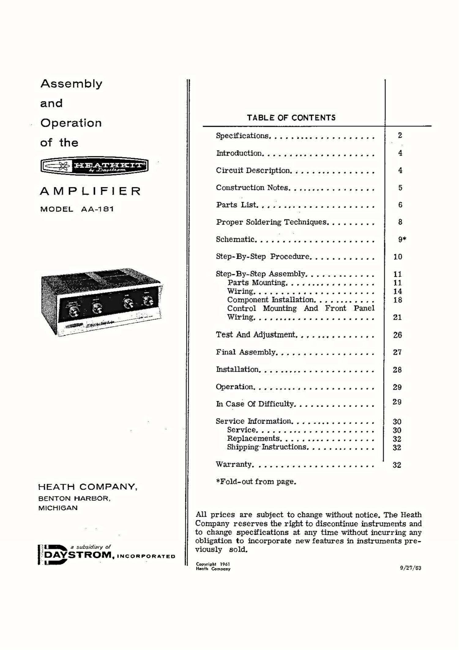
Heathkit AA 181 Service Manual

This is the 38 pages manual for Heathkit AA 181 Service Manual.
Read or download the pdf for free. If you want to contribute, please mail your pdfs to info@audioservicemanuals.com.

Page: 1 / 38
left right
Heathkit AA 181 Service Manual

Extracted text from Heathkit AA 181 Service Manual (Ocr-read)


Page 1

Assembly
and
Operation
of the

Hgyg'EHKIT-a

AMPLIFIER

MODEL AA-181

HEATH COMPANY,

BENTON HARBOR,
MICHIGAN

a subsidiary oI

:_
{EDAYSTROIVL INCORPORATED
it" - '

TABLE OF CONTENTS
Specifications. . . . . ~. .............. 2
Introduction. . . . . . . .............. 4
Circuit Description. .- .............. 4
ConstructionNotes................. 5
Parts List. . . .. ............... 6
Proper Soldering Techniques. ........ 8
Schematic ..... V . .t ............... 9*
Step-By-Step Procedure ............ 10
Step-By-Step Assembly. . . . ....... . . 11
PartsMounting................. 11
Wiring ........ 14
Component Installation. . . . . . . . . . . . 18
Control Mounting And Front Panel
Wiring......... .............. 21
Test And Adjustment. . . . . . . . ..... . . 26
Final Assembly ..... . . . . . . . . ..... 27
Installation ..... . ................ 28
Operation..,........ ............ 29
In Case or Difficulty ............... , 29
Service Information. . . . . . . . . . . ..... 30
Service ....... .. . . . . ......... 30
Replacements. . . . . . . ........... 32
Shipping Instructions ............. 32
Warranty ...... . . . . . . .......... 32

*Fold-out from page.

All prices are subject to change without notice. The Heath
Company reserves the right to discontinue instruments and
to change specifications at any time without incurring any
obligation to incorporate new features in instruments pre-
viously sold.

C ' h! 1961
szg'SCun-pqny 9/27/63

Page 2

Page 2

-Heessrm
SPECIFICATIONS
Power Output ................ . . . . . . . . 25 watts.
Music Power Rating. . . . . . . . . ........... 30 watts.
Peak Power ......................... 50 watts.
Frequency Response ................... 5:1 db from 30 to 15,000 cps at 25 watts (using

Input Sensitivity -

Microphone.............. ...... ..
Magnetic Phono ...................
Crystal Phono ........ . ...........

Auxiliary.......................
Input Iznpedances -

Microphone ......................

Magnetic Phono ............ . . . . . . .

CrystalPhono....................

Auxiliary. ........ . .............
Outputlmpedances....................
DampingFactor ...... ................
Feedback..........................

Harmonic Distortion ...................

Intermodulation Distortion. . . . . . .. . . . . . . .
HumAndNoise-
Microphone. . . ..................
MagneticPhono............ .......
Crystal Phono. ....... ......

AudliarYIlonvlvtoovlvllvnvieono!

Auxiliary input).

9 millivolts rms for 25 watts output.
5 millivolts rms for 25 watts output.
.12 volt rms for 25 watts output.

.2 volt rms for 25 watts output.

1 megohm.
47,000 52.

2.2 megohm.
470,000 52.

4, 8, and. 16 e.
9.

20 db negative feedback at 1000 cps.

0.7% or less at 25 watts, 1000 cps.
2% or less at 25 watts, 30 and 15,000 cps.

2% or less at 25 watts, 60 and 6000 cps, mixed
4:1.

60 db or better.

53 db or better,

. below 25 watts
55 db or better.

60 db or better.

NOTE: Hum and noise measurements were made
with the-inputs shorted, the VOLUME control
fully clockwise, and the tone controls in their
flat positions. The Amplifier output was termi-
nated with a 16 S2 resistive load.

Page 7

Page 7

Haesfixs"
PART PARTS DESCRIPTION
N0. Per Kit

Transformers-Diode-Tiibes

51-82 1 Output transformer '

54-1 1 8 1 Power transformer
E] 57-22 1 Selenium diode

411-25 1 12AU7/ECCBI tube

411-- 1 36 1 GZS4/5AR4 tube

411-138 2 7591 tube

411-143 2 6EU7 tube

El
Terminal Strips-Sockets

2} 431-2 2 Z-lug terminal strip with #6
mounting hole

431-3 1 3-1ug terminal strip with #6
mounting hole
431-5 3 4-lug terminal strip with #6
mounting hole
['11 431-13 1 4-lug screw type terminal
strip
(B 431-32 1 2-1ug terminal strip with #8
mounting hole
431-33 1 3-lug terminal strip with #8
mounting hole
434-2 3 Octal tube socket
434-16 3 Wafer tube socket
434-20 1 AC socket
6] 434-76 1 Triple phone socket
[E 436-4 1 Phone jack
481-1 1 Capacitor mounting wafer
(metal)
481-3 1 Capacitor mounting wafer
(fiber)

PART PARTS
No. Per Kit

DESCRIPTION

Metal Parts

90-M173F 1 Cabinet shell
200-M300F502
1 Chassis
203-M247F503
1 FrOnt panel
203-M248F504-505
l Trim strip
205- M306 1 Bottom plate
210-16F 1 Bezel
Hardware
L73; 250-49 6 3-48 x 1/4" screw
m. 250-32 6 6-32 x 3/8" screw (flat head)
@ 250-26 4 6-32 x 5/8" screw

@5 250-89 9 6-32 x 3/8 screw

owl Imam GIMME annual)

:1 250- 56 11 6-32 x 1/4" screw
[Iii 250-8 7 #6 sheet metal screw
IQ 252-1 6 3-48 nut
E1] 252-3 34 6-32 nut
may all; @ o @
ES: 252-4 8 8-32 nut
ES] 252-7 5 Control nut
[71 252-32 1 Push-on speednut
LI, 253-10 5 Flat washer
as @
@y
1?» 254-1 40 #6 lockwasher
254-2 10 #8 lockwasher
t3! 254-4 4 Control lockwasher
@ 255-2 4 #6 x 3/16" spacer
$1 255-3 4 #6 x 3/8" spacer

@653 I.@@®8 E31'

Wire-Sleeving

89-1 1 Line cord

343-6 1 Length shielded cable

344-1 1 Length hookup Wire

346-1 1 Length insulating sleeving,
black

346-2 1 Length insulating sleeving,

clear

Page 21

Page 21


FRONT PANEL

FRONT APRON

CONTROL MOUNTlNG AND FRONT PANEL
WIRING

( ) Referring to Detail 4A, install the trim
strip using #6 hardware as shown. Do not
pinch any of the wires on the bottom of the
chassis.


/ ' 6 LOCKWASHER
»/:::::::T\\\\ 6-32 NUT
/ I.

5-32): V4" SCREW

Detail 4A
Refer to Pictorial 4 for the following steps.

( ) R22. Position the front panel as shown in
Pictorial 4 and mount a 1 megohm control
with SPST switch (#19-37) at T. Use a
control lockwasher, flat washer, and control '
nut as shown in Detail 43. Do not tighten.

RHJNKW
PILOT LAMP

Pictorial 4


PUSH-ON
SPEEDNUT

f .-
G-NEON LAMP

FRO NT
PAN EL

( ) Similarly mount a 1 megohm control (#10-
64) at U. Do not tighten.

FRONT PANEL.
CHASSIS APRON

CONTROL
LOCKWASHER

CONTROL NUT

CON TROL
FLAT WASHE

Detail 4B

( ) Mount a 1 megohm control (#10-86) at W.
Position as shown in Pictorial 4. Do not
tighten.

( ) Mount the SELECTOR switch (#63-270) at
X. Use a flat washer and control nut. Fit
the tab of the switch into the slot on the
rear of the chassis front apron. Nowtighten
all four Control nuts.

( ) Install the neon pilot lamp in hole S, using
a push-on speednut as shown in Pictorial 4.