Heathkit AA 181 Schematic

This is the 38 pages manual for Heathkit AA 181 Schematic.
Read or download the pdf for free. If you want to contribute, please mail your pdfs to info@audioservicemanuals.com.

Page: 1 / 38
left right
Heathkit AA 181 Schematic

Extracted text from Heathkit AA 181 Schematic (Ocr-read)


Page 1

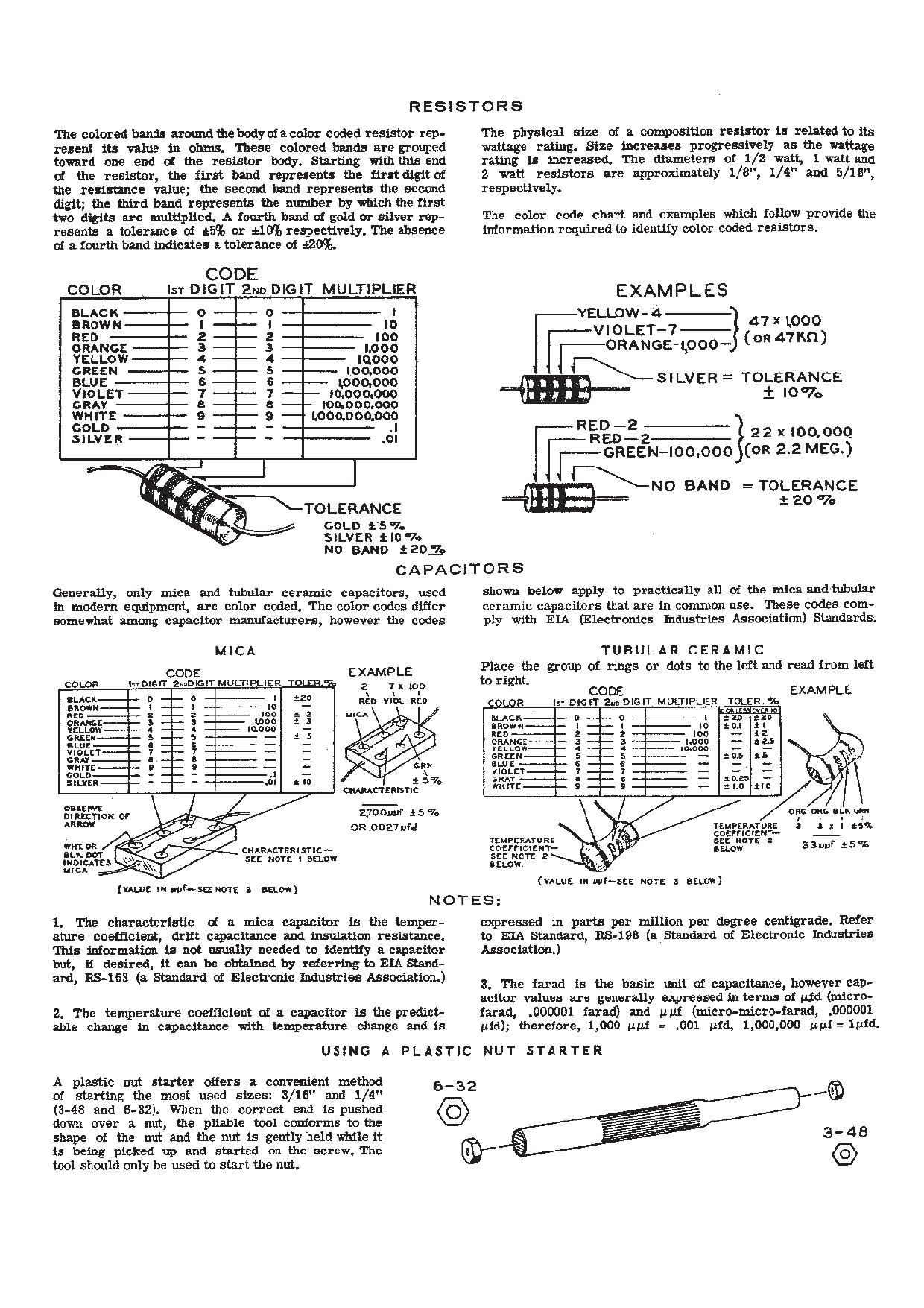
RESISTORS

The colored bands around. the bodyofacolor coded resistor rep-
resent its value in ohms. These colored hands are grouped
toward one end of the resistor body. Starting withthisend
oi the resistor, the first band represents the first digit of
the resistance value; the second hand represents the second
digit; the third hand represents the number by which the first
two digits are multiplied. A fourth hand of gold or silver rep-
resents a tolerznco out e555 or 540% respectively. The absence
of a fourth band indicates a. tolerance of £265.

CODE

COLOR ls'r DiGlT 2m DIGET MULTiPLiER
BLACK 0 o I
anown I I In
use 2 2 Ion
ORANGE e s moo
YELLOW 4 4 Iqooo
cases 5 s Ioo.ooo
BLUE 5 5 1,000,000
VIOLET 7 7 Io.ooo.ooo
can a e "30.000.000
WHITE 9 e - Loonoooooc
coLo , - - .I
SILVER - - .cI
1-1
\ hTOLERANCE
, 4 GOLD e s v.

SILVER tIO '7-
No BAND $203,

The physical size of a composition resistor is reletedtc its
wattage rating. Size increases progressively as the wattage
rating is increased. The diameters of 1/2 watt, 1 wattand
2. watt resistors are approximately 1/8", 1/4" and 5/16",
respectively.

The color code chart and examples which follow provide the
iniormation required to identity color coded. resiStors.

EXAMPLES
_vELI_OW-4-
41 new
VIOLET-7 -} (0R 47m)

l-ORANGE-LOOO-
_mr_\ SILVER = TOLERANCE

I I070
-RED -2

enco-

r-GREEN-IDOfiOO
=mr>NO BAND =TOLERANCE

22 X 30.000
(on 2.2 MEG.)

i20'7o

CAPACITORS

Generally, only mice and tubular ceramic capacitors, used
in modern equipment, are color coded. The color codes differ
somewhat among capacitor manufacturers, however the codes

shown below apply to practically all of the mica and-nebular
ceramic capacitors that are in common use. These codes com-
ply with EIA (Electronics Industries Association) Standards;

MICA TUBULAR CERAMIC

CGDE EXAMPLE Place the group of rings or dots to ihe left and read from left
coma hrDlGJT EunDDGIT MULTIPLIER Tome. 2 7 no to right, CODE EXAMPLE
3:33; 2 :1: 3 I; 3:" use wet it CQLQR g £1:ch ZunDIGIT MULTIPLIER Tutti:

_ a
33m: § ~ g J33 é a 'c" sues - a gen
erLow 4 - n mono - I ecu
class 5 w- e - a s 2 -
thitn % 9 - I 3 :2
mm a o _ - s x no
231'? z 2 -. : g :
SILVEI - - - - .él : In a: I soles
ems-sermon: I e Ito
35%;? or 2,700uuf .t 5 7: one one lil.K an:
Hm OR .0027 M TEMPERATURE J a a I 45-;
IEHPCRATHRE §E§Tfi§"§'
3:237 CHARACTERISl'ltv- cosrnclsm- erLow asuui :51
wow, 5:: N011 I am:- 5:: NOT: 2
me»
"M; m nut-S: N": a same) (um: IN nub-use: N07: 3 scum)
N O T ES :

l. The characteristic of a nice capacitor is the temper-
ature coefficient, drift capacitance and insulation resismnce.
This information is not usually needed to identify a capacitor
but, if desired, it can be obtained by referringto Em Stand-
ard, 128-163 (a Standard oi! Electronic Industries Association.)

2. The temperature coefficient of a capacitor is the predict-
able change in capacitance with temperature clause and is

expressed in parts per million per degree centigrade. Refer
to EIA Standard, IRS-193 (a Standard of Electronic Industries
Association.)

a. The fnxarl is the basic unit oi capacitance. however cap-
acitor values are generally eicpressed in terms at Id (micro-
fuad, .000001 fared) and out (micro-micro-isrsd, .000001
std); therefore, 1,000 tipi = .001 gird, 1,000,000 uuf=1uicL

USING A PLASTIC NUT STARTER

A plastic nut starter offers a. convenient method
oat starting the most used sizes: 3/16" and 1/ "
(3-48 and 6-32). When the correct end Is pushed
down over a nut, the pliable tool conforms tothe
shape of the nut and the nut is gently held while it
is being picked up and started on the screw. The
tool should only be used to start the not,

Page 2

Assembly

and

Operation
of the

HEfifEEI-IKIT

AMPLIFIER

MODEL AA-181

HEATH COMPANY,
BENTON HARBOR,
MICHIGAN

a subsidiary of

31
iDAYSTROM. INCORPORATED
I...

TABLE OF CONTENTS

Specifications. . . . . . .............. 2
Introduction..................... 4
Circuit Description ................ 4
ConstructionNotes.........,....... 5
PartsList....... ............... 6
Proper Soldering Techniques. ........ 8
Schematic...................... 9*
Step-Bywstep Procedure ............ 10
Step-By-Step Assembly. . . . . . . . , . . . 11
PartsMounting............. 11
Wiring ........ 14
Component Installation. . . . . . . . . 18
Control Mounting And Front Panel
ermg 21
Test And Adjustment. . . . . . . . ..... . . 26
FinalAssembly ..... 27
Installation ..... . ................ 28
Operation....................... 29
In Case or Difficulty ............... 29
Service Information. . . . . .. . . . . ..... 30
Service ....... . . . . . . ......... 30
Replacements................. 32
Shipping- Instructions ............. 32
Warranty............ .......... 32

*Fold- out from page.

All prices are subject to change without notice. The Heath
Company reserves the right to discontinue instruments and
to change specifications at any time without incurring any
obligation to incorporate new features in instruments pre-
viously sold.

C M I963
HZZKZBCWWW 9/27/53

Page 24

( ) Referring to Detail 513, connect the P.E.C.

lead coming from hole K to lug Z of ter-
minal strip BE (8-6). Connect the P.E.C.
lead coming from hole L to lug 4 of
terminal strip BB (5-2).

we

Detail 5B \

Connect the remaining P.E.C. leads as follows:
P.E.C. LEAD

NUMBER TO LUG

( )7 1 of control T (8-1).
( )6 2 of control T (NS).
( )3 3 of control T (5-1).
( )5 l of control U (8-1).
( )4 2 of control U (S-l).
( )2. 3 of control U (S-l).

(

Page 23

) Connect the inner lead of the shielded cable
coming up through hole N to lug 2 of con-
trol T (8-2). Make sure the clear plastic
sleeving is in the position shown in Pic-
torial 5.

w

Slip a 3/4" length of the clear plastic
sleeving over each wire of the twisted
pair coming through grommet J.

V

Connect either lead of this twisted pair
to lug 4 of control T (Sui).

) Connect the other lead to lug 5 of control
T (5-1).

Push the sleeving on both wires over the
solder lugs and against control T.

Cut both leads of the neon pilot lamp to
approximately 1/2" in length,

V

Slip 3. 1 length of sleeving over each wire
of the twisted pair coming up through
grommet M.

) Connect either lead of this twisted pair to
one of the leads of the neon pilot lamp
(8-1). New push the cleaving up over the
soldered connection and against the pilot
lamp.

) Solder the other lead of the twisted pair to
the remaining lead of the pilot lamp (S-l).
Now push the sleeving up over this soldered
connection and against the neon pilot lamp.

Page 29

Page 28

INSTALLATION

CHANGER WlTH
X'I'AL PHONE
CARTRIDGE.

TURNTABLE WITH
MAGNETIC PHDNO
CARTRIDGE.


H lGH FMPEDANCE
MICROPHONE

ulnar-J

e 8
o o e c
Aug ,5 gt @ Ml

7va AC
3AM?

E UNSWITCHED

SYSTEM

C4RBD35
W @KES Q ea®8®ej
U Us: I

TO SPEAKER

Pictorial 9

Because of its attractive styling, the Amplifier
may be placed in the open or, if desired, it may
be panel mounted, usingthe mounting dimensions
listed in the Specifications section of the manual.
Mounting in a horizontal panel, with the chassis
vertical, is not recommended.

Since heat is normally generated in all power
amplifiers, adequate ventilation around the cabi-
net is very important. At least one inch of open
space behind the Amplifier and three inches
of space above the cabinet is considered mini-
mum for proper air circulation.

Pictorial 9 shows a typical high fidelity instal-
lation of the Amplifier. This installation is
provided simply as an example and shouldbe used
only as a guide for installing your system. There
are, of course, manyotherpossible combinations
of equipment that will provide equally good
results.

X'TAL PHONO -

INPUT CONNECTIONS

Shielded cables terminated in appropriate plugs
should be used to make input signal connections
to the Amplifier.

MIC - The MIC input is provided for use with
most high- impedance microphones.

MAG PHONO - Low level magnetic and re-
luctance type phone pickup cartridges should be
played through this input. RIAA equalization is
provided.

Crystal and ceramic type
phono pickup cartridges should be played through
this input. Compensation is provided for a
proper frequency response when used with
crystal and ceramic cartridges,

Page 30

I-IEAgII-IKIT!
A. .44... mm

NOTE: The XTAL input can be modified for
use as an additional AUX input by removing
C1 and changing the values of R3 and R4 to
correspond to the values of R5 and R6. Refer
to the Schematic Diagram. The necessary re-
sistors should be obtained locally.

AUX - The AUX input can be used with most
transformer - operated, high ~ level signal
sources, such as tuners, tape recorders, etc.

Page 29

SPEAKER - Connections from the amplifier

to the speaker system maybe made with standard
AC lamp cord or flat television antenna lead-in
wire. Lamp cord is considered preferable for
this application.

AC OUTLET - The AC outlet on the rear of the
chassis is unswitched and may be used to
provide power for accessory equipment used
with the Amplifier.

OPERATION

Operation of the Amplifier is convenient and
straightforward. Simply choose the desired
input with the SELECTOR switch, and set the

VOLUME, BASS, and TREBLE controls for the

desired listening level and tone.

IN CASE OF DIFFICULTY

1. Recheck the wiring. Trace each lead in
colored pencil on the Pictorial as it is
checked. It is frequently helpful to have a
friend check your work. Someone whois not
familiar with the unit may notice something
consistently overlooked by the constructor.

2. It is interesting to note thatabout 90%of the
kits that are returned for repair, do not
function properly clue to poor connections
and soldering. Therefore, many troubles
can be eliminated by reheating all connec-
tions to make sure that they are soldered
as described in the Proper Soldering Tech-
niques section of this manual.

3. Check to be sure that all tubes are in their
proper locations. Make sure that all tubes
light up properly.

4. Check the tubes with a tube tester or by
substitution of tubes of the same types
and known to be good.

5. Check the values of the component parts.
Be sure that the proper part has been
Wired into the circuit, as shown in the
pictorial diagrams and as called out in the
wiring instructions.

6. Check for bits of solder, wire ends or other
foreign matter which may be lodged in the
wiring.

7. If. after careful checks, the trouble is still
not located and a voltmeter is available,
check voltage readings against those found
on the Schematic Diagram. NOTE: All
voltage readings were taken with an 11
megohm input vacuum tube voltmeter. Volt-
ages may vary as much as 10% due to line
voltage variations.

8, A review of the Circuit Description will
prove helpful in indicating where to look
for trouble.