Heathkit AA 151 Notice Montage Kit 18 a 39

This is the 22 pages manual for Heathkit AA 151 Notice Montage Kit 18 a 39.
Read or download the pdf for free. If you want to contribute, please mail your pdfs to info@audioservicemanuals.com.

Page: 1 / 22
left right
Heathkit AA 151 Notice Montage Kit 18 a 39

Extracted text from Heathkit AA 151 Notice Montage Kit 18 a 39 (Ocr-read)


Page 1

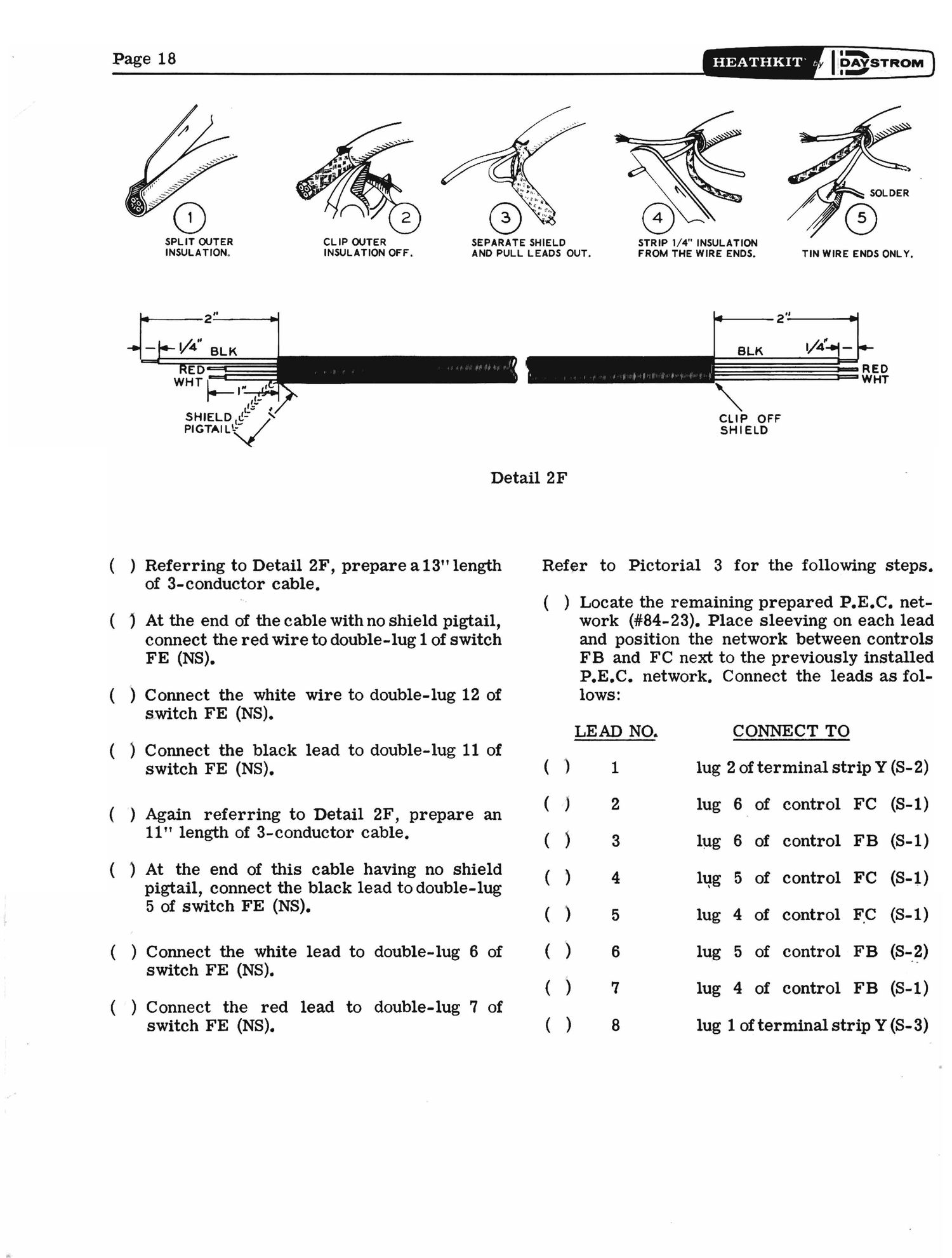
SPLIT OUTER CLIP OUTER SEPARATE SHIELD
INSULATION, INSULATION OFF. AND PULL LEADS OUT. FROM THE WIRE ENDS. TIN WIRE ENDS ONLY.

[.5 4'

SHIELD (g-
PIGTAILV

Detail 2F

( ) Referring to Detail 2F, prepare a13" length
of 3-conductor cable.

( ) At the end of the cable with no shield pigtail,

connect the red wire to double-lug 1 of switch
FE (NS).

( ) Connect the white wire to double-lug 12 of
switch FE (NS).

( ) Connect the black lead to double-lug 11 of
switch FE (NS).

) Again referring to Detail 2F, prepare an
11" length of 3-conductor cable.

( ) At the end of this cable having no shield

pigtail, connect the black lead to double-lug
5 of switch FE (NS).

( ) Connect the white lead to double-lug 6 of
switch FE (NS).

( ) Connect the red lead to double-lug 7 of
switch FE (NS).

I
HEATHKIT by I DAVSTROM
I-

STRIP 1/4" INSULATION

I p ;|» u n :I 4v y) I1 I' H

CLIP OFF
SHIELD

Refer to Pictorial 3 for the following steps.

( ) Locate the remaining prepared P.E.C. net-

(

)

v v V

work (#84-23). Place sleeving on each lead
and position the network between controls
FB and FC next to the previously installed
P.E.C. network. Connect the leads as fol-
lows:

LEAD NO. CONNECT TO
1 lug 2 of terminal strip Y (S-2)
2 lug 6. of control FC (8-1)
3 lug 6 of control FB (S-1)
4 lug 5 of control FC (8-1)
5 lug 4 of control FC (8-1)
6 lug 5 of control FB (312)
7 lug 4 of control FB (S-1)
8 lug 1 of terminal strip Y(S- 3)

Page 2

l . iv 7777
31:. 5555

#
6 L:C:WA$HER\ I
2 NUT\3


Pictorial 4

Refer to Pictorial 4 for the following steps. ( ) Connect a 1-1/2" length of hookup wirefrom

( ) Locate the center shield and mount a
triple phono socket with an insulator at
location BH on the center shield. Use
6-32 x 3/8" screws, #6 lockwashers and
6-32 nuts. Refer to Detail 4A for proper
orientation of the phono socket.

( ) Similarly mount a triple phono socket and
insulator at location BJ. Use 6-32 x 3/8"
screws, #6 lockwashers and 6-32 nuts.

( ) Mount a 4-1ug terminal strip at location BK
on the center shield. Use #6 hardware.

( ) Mount a 3-lug terminal strip at location
BL on the center shield. Use #6 hardware.

( ) Mount the center shield to the top of the
main chassis. Use 6-32 x 3/8" screws,
#6 lockwashers, and 6-32 nuts.

Refer to Detail 4A for the following steps.

( ) Connect a 2" length of hookup wire be-
tween lugs 2 (S-1) and 5 (NS) of phono
socket BH.

SUBPANEL

I...-
FE
#

I
HEATHKIT o IPAXSTROM

.........

''''''''
--------

o '.
.......

......

ILOT LAMP

n .
...........
v a I
.......
.:-I:-
-----------

PANEL
CONTROL PANEL

lug 5 of phono socket BH (NS) to lug 5 of
phono socket BJ (NS).

( ) Connect another 1-1/2" length of hookup

wire from lug 5 of phono socket BH (8-3)
to lug 4 of terminal strip BK (NS).

( ) Connect one end of an 8" length of hookup

wire to lug 4 of terminal strip BK (NS).
Place the free end of this wire through
hole HQ in the chassis. It will be con-
nected later.

FROM TOP OF
SWITCH FE

.-

+FR0M 301mm or
swu'rcu FE

Detail 4A