Heathkit AA 121 Assembly Operation

This is the 41 pages manual for Heathkit AA 121 Assembly Operation.
Read or download the pdf for free. If you want to contribute, please mail your pdfs to info@audioservicemanuals.com.

Page: 1 / 41
left right
Heathkit AA 121 Assembly Operation

Extracted text from Heathkit AA 121 Assembly Operation (Ocr-read)


Page 1

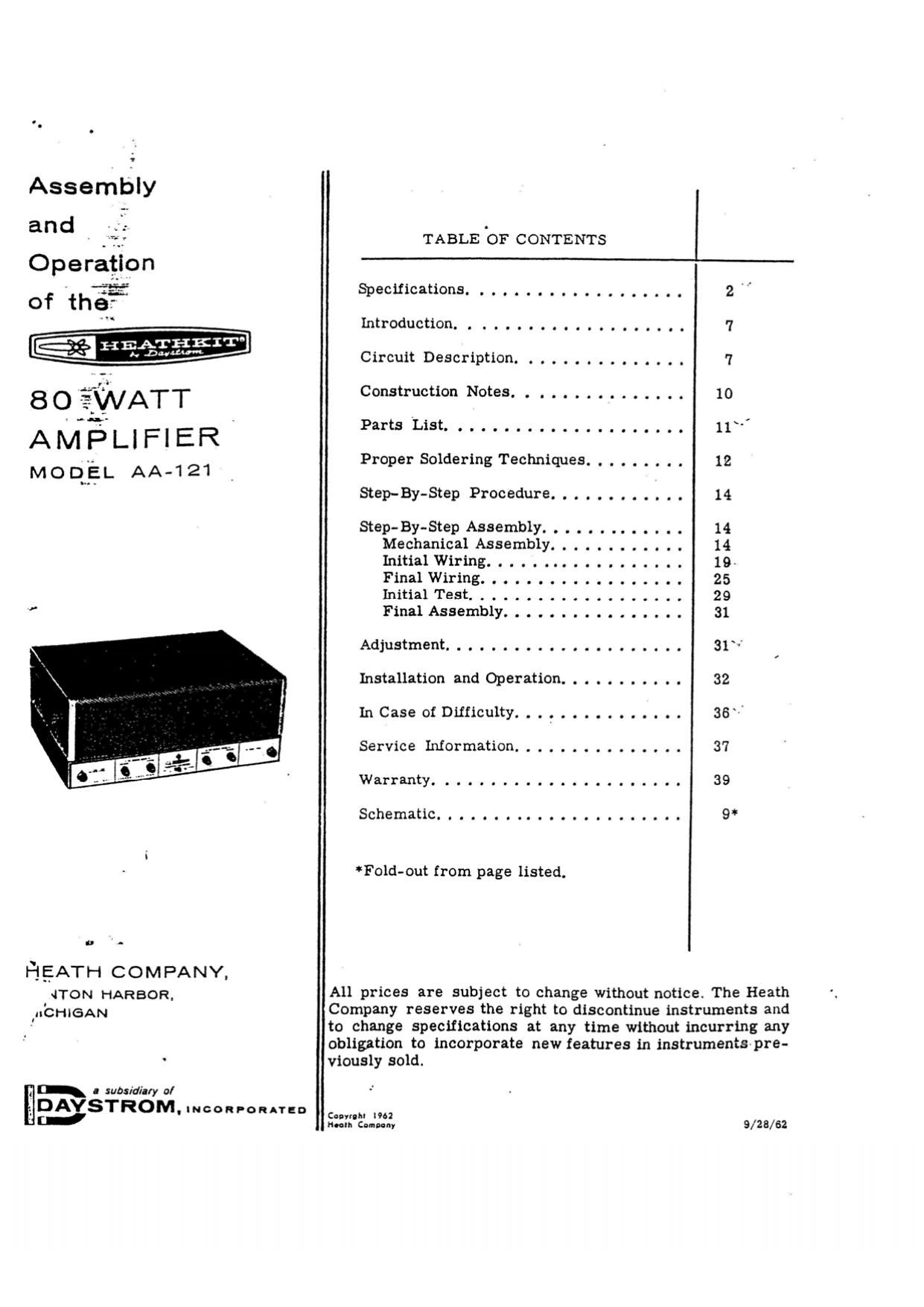
Assembly
and

Operation
of thef

HE%E§EIT°

AM'ELIFIER'

MODEL AA-121

u -

HEATH COMPANY,

{TON HARBOR.
IIICHIGAN

. subsidia/y o/

DAYSTROM
. INCORPORAYED

TABLE '01? CONTENTS

Specifications................... 2
Introduction................... 7
Circuit Description. 7

Construction Notes. . . . . . . . . . . . . . . 10
PartsList..................... l1
Proper Soldering Techniques. . . . . . . . . 12

Step-By-Step ProcedurE. . . . . . . . . . . . 14

Step-By-Step Assembly. . . . . . . . . . . . . 14
Mechanical Assembly. . . . . . . . . . . . 14
InltiaiWiring.................. 19-
FinalWiring.................. 25
Initial Test. . . . ....... . . ...... 29
Final Assembly. . . ...... . . . . . . . 31

Adjustment..................... 31

Installation and Operation. . . . ...... . 32

InCaseofDifficulty............... 36"

Service Information ............... 37
Warranty...... ........ 39
Schematic............... ..... .. 9*

Fold-out from page listed.

All prices are subject to change without notice. The Heath
Company reserves the right to discontinue instruments and
to change specifications at any time without incurring any
obligation to incorporate new features in instrumentspre-
viousiy sold.

C h I?
"Zli'cl..." 9/25/52

Page 2

Page 2

_m:.eemnr

THE HEATHKIT

80 WATT' AMPLIFIER .
MODEL AA-12l

SPECIFICATIONS

The following specifications are presented in the
belief that you are entitled to a factual and com-
prehensive technical report on the performance
of the Model AA-lZi Amplifier.

These specifications are based on measurements

made on a number of AA-121 Amplifiers, con-
structed by individuals who represent various
levels of technical skill. The measurements
were made under carefully controlled conditions,
not to present the most favorable advertising
information but in strict accordance with gener-
ally accepted standards.

Page 20

Page 20

( ) At one end oi a 5-1/ " twistedpair, connect
the green wire to lug 5 (8-1) and the yellow
wire to lug 4 (8-1) at tube socket V1.

( ) At the other end, connect the green wire to
lug 7 (NS) and the yellow wire to lug 2 (NS)
of tube socket V3.

( ) At one end oi a 5" twisted pair, connect the
green wire to lug 7 (S-2) and the yellow wire
to lug 2 (5-2) of tube socket V3.

( ) At the other end, connect the green wire to
lug 7 (NS) andthe yellow wire to lug 2 (NS)
oi tube socket V5.

( ) At one end oi a 4-1/2" twisted pair connect
the green wire to lug 7 (8-2) and the yellow
wire to lug 2 (S-2) 01 tube socket V5.

( ) At the other end, connect the green wire to
lug 1 (NS) and the yellow wire to lug 2 (NS)
of terminal strip 3.

( ) At one end oi a 5" twisted pair, connect the
green wire to lug 5 (NS) and the yellow wire
to lug 6 (NS) 01 terminal strip H.

( ) At the other end, connect the green wire to
lug 7 (NS) and the yellow wire to lug 2 (NS)
oi tube socket V4.

( ) At one end oi a 4-1/2" twisted pair, connect
the green wire to lug 7 (NS) and the yellow
wire to lug 2 (NS) oi tube socket V4.

( ) At the other end, connect the green wire to
lug 7 (S-1) and the yellow wire to lug 2
(8-1) 0! tube socket V6.

( ) At one end 01 a 5-1/2" twistedpair, connect
the green wire to lug 7 (8-3) and the yellow
wire to lug 2 (8-3) at tube socket V4.

( ) At the other end, connect the green wire to
lug 5 (5-1) and the yellowwiretolug 4 (S-1)
oi tube socket V2.
Refer to Pictorial 3 (told-out from Page 25)
tor the iollowing steps.

( ) Referring to Detail 3A, bend the two center
lugs oi switch BB outward as shown. This
will provide additional space between the
switch lugs and thereby minimize the possi-
bility oi short circuits in the wiring of this
switch.

BEND
CENT E R
LUGS :
OUTWARD

Detail 3A

NOTE: Use the orange hookup wire inthe follow-
ing steps. Dress the hookup wires against the
chassis and under the transformer leads which
are already connected.

( ) Strip 3/4" of insulation irom one end and
1/4" irom the other end of a 2" wire. Con-
nect the 3/4" stripped end through lug 4
(NS) to lug 5 (8-1) of phone jack AA.

( ) Connect the other end oi this wire to lug l
oi phone jack AA (NS).

( ) Connect a 1-1/4" wire from lugZoiterminal
strip DD (5-1) to lug 5 of switch BB (S-l).

( ) Connect a 2-3/4" wire from lugl oiterminal
strip DD (8-1) to lug 2 of switch BB (S-l).

( ) Connect a 1" wire from lug 1 (NS) to lug 6
(NS) of switch BB.

( ) Connect another 1" wire from lug 4 (S-l)to
lug 3 (NS) of switch BB.

( ) Connect a 5" wire from lug 6 of switch BB
(8-3) to lug l of terminal strip Hl-l (NS).

( ) Connect a 6" wire from lug 2.0i terminal
strip Ill-l (5-1) to lug l of terminal strip LL
(8-2).

( ) Connect a 1-1/2" wire from lug 2 of AC
socket SS (NS) to lug 2 oi iuse holder JJ
(5-1).

( ) Connect a 1-1/2" wire from lug 2 oi AC
socket N'N (NS) to lug 2 at AC socket SS (S-Z).

( ) Connect an 8-1/4" wire from lug 2 of sur-
($13?" RR (8-1) to lug l of AC socket 88
NS .

) Connect a 9" wire from lug 5 of terminal
(stri)p DD (5-2) to lug 3 ct terminal strip E
NS .

v.4

Page 23

Hsceflznr

(
(
(

(

Page 23

==a=~
Detail 3D ' if]:

F-"fl

) Connect the longer shield lead to lug 4 of
phone jack AA (5-3).

) Connect the inner lead at this end of the
cable to lug 3 of pheno jack AA (5-1).

) At the other end of this cable, connect the
inner lead to lug 4 (NS) and the shield lead
to lug 3 (N8) of terminal strip QQ.

) Prepare a length of l-conductor shielded
cable as indicated in Detail 3E.

) Connect the longer inner lead to lug 3 of
control U (S-l).

) Connect the shield lead at this end of the
cable to lug l of control U (5-3).

) At the other end of this cable, connect the
inner lead to lug 2 (S-1) and the shield lead
to lug 1 (5-2) of phone jack AA.

) Prepare a l-conductor shielded cable as
indicated in Detail 3!".

) Connect the longer inner lead to lug 3 of
control Z (8-1).

) Connect the shield lead at this end of the

cable to lug l of control 2 (5-2).

Dress this cable along the front of the chas-

sis. At the free end of the cable, connect

the inner lead to lug 4 (5-2) and the shield
lead to lug 3 (8-2) of terminal strip QQ.

v

Iir.
#-

Detail 3E

.Iy.

( ) Prepare a length of Z-conductor shielded
cable as indicated in Detail 3G.

( ) At the end of this cable Without a shield

lead, connect the yellow lead to lug 1 of AC

socket NN (NS).

Connect the green lead at this end of the

cable to lug l of AC socket SS (8-2).

( ) Dress this cable around the lower left
corner of the chassis and toward .control
U. The cable should be beneath the secondary
leads of the A Channel output transformer.

( ) Remove the AC switch coverfrom controlU
and slip it over the free ends of the green and
yellow leads.

( ) Connect the green leadcf this cable to either
lug on the rear of control U (S-l).

( ) Connect the yellow lead to the other lug on
the rear of control U (S-l).

( ) Carefully place the AC switch cover over
the rear section of control U, then solder
the shield lead of the cable to the outside of
the AC switch cover as shown in Pictorial
3.

,-

Page 37

Page 37

-HEATHEFIT'

SERVICE

If, after applying the information in this manual
and your best efforts, you are still unable to
obtain proper performance, it is suggested
that you take advantage of the technical facil-
ities which the Heath Company makes avail«
able to its customers,

T_he Technical Consultation Department is main-
tained for your benefit. This service is available

to you at no charge. Its primary purpose is to
provide assistance for those who encounter
difficulty in the construction, operation or
maintenance of HEATHKIT equipment. It is not
intended, and is not equipped to function as a
general source of technical information involving
kit modifications nor anything other than the
normal and specified performance of HEATHKIT
equipment.

Although the Technical Consultants are familiar
with all details of this kit, the effectiveness of
their advice will depend entirely upon the amount
and the accuracy of the information furnished by
you. in a sense, YOU MUST QUALIFonr GOOD
technical advice by helping the consultants to
help you. Please use this outline:

1. Before writing, fully investigate each of the
hints and suggestions listed in this manual
under "IN CASE OF DIFFICULTY." Pos-
sibly it will not be necessary to write.

2. When writing, clearly describe the nature
of the trouble and mention all associated
equipment. Specifically report operating
procedures, switch positions, connections
to other units and anything else that might
help to isolate the cause of trouble.

3. Report fully on the results obtained when
testing the unit initially and when following
the suggestions under "IN CASE OF DIF-
FlCULTY. " Be as specific as possible and
include voltage readings if testequipment is
available.

4. Identify the kit model number and date of
purchase, if available. Also mention the
date of the kit assembly manual. (Date at
bottom of Page 1.)

5. Print or type your name and address,
preferably in two places on the letter.

With the preceding information, the consultant
will. know exactly what kit you have, what you
would like it to do for you and the difficulty you
wish to correct. The date of purchase tells him
whether or not engineering changes have been
made since it was shipped to you. He will know
what you have done in an effort to locate the
cause of trouble and, thereby, avoid repeti-
tious suggestions. In short, he will devote full
time to the problem at hand, and through his
familiarity with the kit, plus your accurate
report, he will be able to give you a complete
and helpful answer. If replacement parts are
required, they will be shipped to you, subject
to the terms of the Warranty.

The Factory Service facilities are also available

to you, in case you are not familiar enough with
electronics to provide our consultants with suf-
ficient information on which to base a diagnosis
of your difficulty, or in the event that you pre-
fer to have the difficulty corrected in this man-
ner. You may return the completed equipment
to the Heath Company for inspection and neces-
sary repairs and adjustments. You will be
charged a minimal service fee, plus the price
of any additional parts or material required.
However, if the completed kit is returned within
the Warranty period, parts charges will be
governed by the terms of the Warranty. State
the date of purchase, if possible.

Local Service by Authorized HEATHIG'I Serv-
ice Centers is also available in some areas and
often will be your fastest, most efficient method
of obtaining service for your HEATHKIT equip-
ment. Although charges for local service are
generally somewhat higher than for factory serv-
ice, the amount of increase is usually offset
by the transportation charge you would pay if
you elected to return your kit to the Heath
Company.

HEATHKIT Service Centers will honor the
regular 90 day HEATHKIT Parts Warranty on
all kits, whether purchased through a dealer
or directly from Heath Company; however, it
will be necessary that you verify the purchase
date of your kit.

Under the conditions specified in the'Warranty,