Heathkit 337 C Owners Manual 2

This is the 4 pages manual for Heathkit 337 C Owners Manual 2.
Read or download the pdf for free. If you want to contribute, please mail your pdfs to info@audioservicemanuals.com.

Page: 1 / 4
left right
Heathkit 337 C Owners Manual 2

Extracted text from Heathkit 337 C Owners Manual 2 (Ocr-read)


Page 1

HEATHKIT DEMODULATOR PROBE #337-C

The #337-0 Ben-insulator Probe greatly extends the usefulness of any oscilloscOpe. It provides
a means of showing modulation envelopes of RF or IF carriers as found in radio and television
receivers. Thus the oscilloscope can be used as a signal tracer,» again analyzer and an align-
ment indicator. Many other uses will become evident as the user becomes more familiar with
the characteristics of the probe and oscilloscope combination.

A well shielded probe with the defecting elements contained in the housing is necessary for sat-
isfactory indications at high RF frequencies. The Heathkit #33'7-C Demodulator Probe meets
these requirements. Input leads are extremely short in order to eliminate extraneous signal
pickup which can give false readings. The metal probe housing is grounded to prevent hand
capacity effects from causing deflection of the trace. Etched circuit wiring cuts down circuit
capacity, improving high frequency performance.

The input capacitor is rated at 500 voltsDC and the probe should not be applied to circuits where
DC voltages higher than this are found. AC or RF voltages in excess of 30 volts RMS should
not be measured as damage to the crystal diode may result. However, the probe can be con-
nected to high voltage points in a unit, such as the plate of a tube, as long as the DC voltage
present does not exceed the 500 volt DC limit.

* 1. .WI MPD DU:
mama COMB _g_ CRYSTAL m
~ Chm ID 1'0 LIFT.

cam mun
m.mu.m. not Liomnm
on mean "I", imam-successes)
a-- tr
1, V '
1 , 7'}? ~.._ £3 i. mpuPMCflAfll:
I
I ?
FLAT 1 i. I a/r- LINGI'H
\ SIDE % m: was
s -
~
.. . r
..... a _ 0%.,Q, ~ I
O S
- /' . a - a '.
mm . if- .» _ ~. 1,
suave @ a, , \-._
"h- 19h. ..
7. 1 1/!" users
out: was

a. :1 um um
alumna-mos)

XML
3 r i I!
I Lem

DEMODULATOR PROBE 337-C

Page 2

PROBE CONSTRUCTION

NOTE: ALL GUARANTEES ARE VOIDED AND WE WILL NOT REPAIR OR SERVICE
INSTRUMENTS IN WHICH ACID CORE SOLDER OR PASTE FLUXES HAVE BEEN
USED. WHEN IN DOUBT ABOUT SOLDER, IT IS RECOMMENDED THAT A NEW
ROLL PLAINLY MARKED "ROSIN CORE RADIO SOLDER" BE PURCHASED.

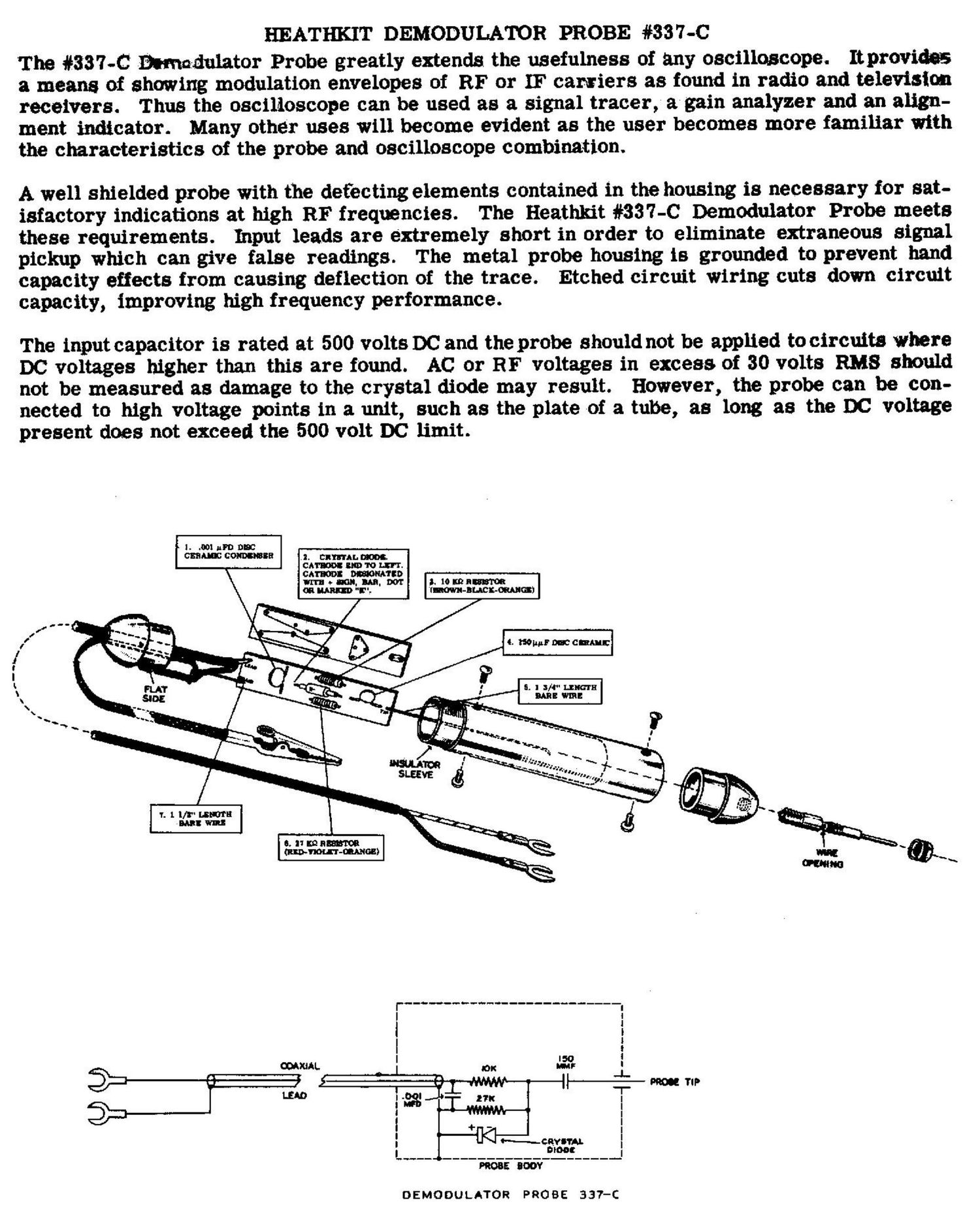
The pictorial clearly shows assembly detail of the probe and etched circuit board. Begin con-
struction by mounting the components on the circuit board in the numbered sequence shown on
the pictorial. All parts will mount on the unmarked side of the board, with their leads coming
out on the etched side. Generally, it is best to mount all components before soldering, bending
the leads over slightly to lock the parts in place. After all parts are secured, the board should
be turned over and each lead soldered at the point where it comes through with a 25 or 50 watt
soldering iron. After soldering, all leads should be clipped off.

For best soldering results, a 25 to 50 watt iron is recommended. The tip. should be clean and
well tinned in order to obtain a quick, clean solder joint. Hold the tip of the iron at the junction
of the component lead and the etched board conductor, and. apply goodquality rosin core solder
at the same point until a good connection is obtained between the two parts. 'When all parts are
clean, the connection can be made very quickly, preventing heat damage to resistors and con-
densers. In order to protect crystal diodes, a clamp, needle nosed pliers or some other type
of heat barrier should be clamped on the diode lead between the diode and connection, on the
opposite side of the board from the connection.

Place the length of flat braid and the shielded cable through the black probe end. Remove 1" of
black outer insulation. Push the braid back until a bulge develops near the end of the outer in-
sulation. Bend the end over, poke a hole in the shield braid and pull center conductor through
as shown. Bend the flat braid and shield braid back together over the flat portion of the probe
end and solder together. Make sure thatthe two braids are as flat-as possible or it, will be dif-
ficult to install the probe body.

Fit the insulator strip tight against the probe end and solder the shield lead coming from the
circuit board to the two braids near the center conductor. Cut the center conductor toa length

sufficient to reach the hole marked "lead. " Strip away 1/8" of insulation-and 'solder the center
conductor at this point. Cut off all excess wire at this end.

Prepare the probe body by inserting the large sleeve. Slip the entire assembly over the circuit
board and rear probe end and secure with two self-tapping screvvs. Install the phone tip in the
red probe end and remove the collar. Insert this end into the probe body, making sure that the
' lead from the circuit board tip appears through the hole at the side of the tip. Secure with the
remaining self-tapping screws. Wrap the wire around the tip in the space provided and reinstall
the collar. Solder an alligator clip to the end of the flat braid.

At the opposite end of the cable, strip away 3" of black outer insulation. Prepare as before .
Solder one spade lug to the shield braid and the other to the end of the center cOnductor. This
completes the assembly of the Demodulator Probe.

USE OF THE PROBE

Standard RF signal tracing techniques can be observed using the oscilloscope and Demodulator
Probe. RF and IF signals can be traced from the second detector of the unit in question back
to the mixer and antenna circuits. The probe can be applied to the grid and plate of each stage
without the necessity of using isolation capacitors, etc. It must be remembered that the sen-
sitivity of the probe is limited by the characteristics of the oscilloscope and it will be difficult to
obtain adequate indications in low level circuits. However, strong signals will uSually be evident
from the grid of the first IF stage to the second detector. Indications in the first stages may
require the use of a signal generator to provide adequate signal level. Television sweep align-
ment procedures are made easier by use of the probe, for it is possible to check waveforms at
different points in the IF circuits as well as the overall bandpass characteristics in tuners and

boosters.
Page 2