Heathkit 336 Owners Manual

This is the 2 pages manual for Heathkit 336 Owners Manual.
Read or download the pdf for free. If you want to contribute, please mail your pdfs to info@audioservicemanuals.com.

Page: 1 / 2
left right
Heathkit 336 Owners Manual

Extracted text from Heathkit 336 Owners Manual (Ocr-read)


Page 1

For VTVMS with 1.5V Full Scale Range
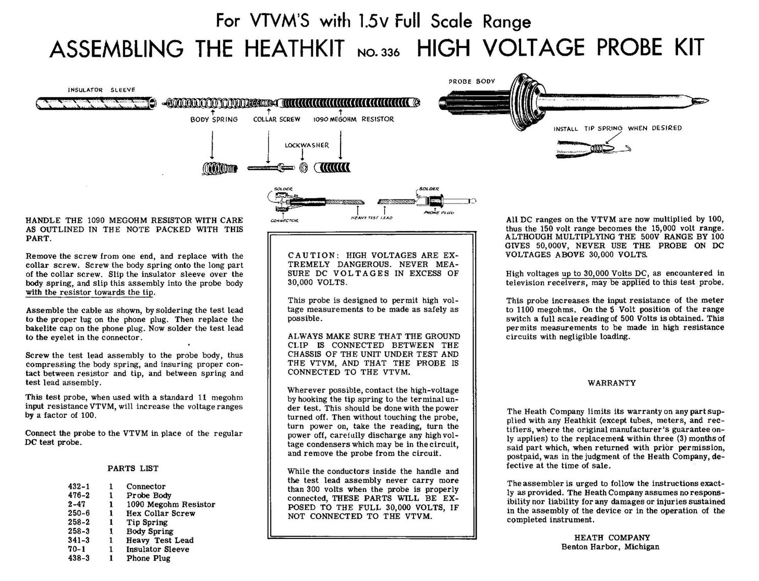
ASSEMBLING THE HEATHKIT No.336 HIGH VOLTAGE PROBE KIT

INSULATOR SLEEVE

BODY SPRING

HANDLE THE 1090 MEGOHM RESISTOR WITH CARE
AS OUTLINED IN THE NOTE PACKED WITH THIS
PART.

Remove the screw from one end, and replace with the
collar screw. Screw the body spring onto the long part
of the collar screw. Slip the insulator sleeve over the
body spring, and slip this assembly into the probe body
with the resistor towards the tip.

Assemble the cable as shown, by soldering the test lead
to the proper tug on the phone plug. Then replace the
bakelite cap on the phone plug. Now solder the test lead
to the eyelet in the connector.

Screw the test lead assembly to the probe body, thus
compressing the body spring, and insuring proper con-
tact between resistor and tip, and between Spring and
test lead assembly.

This test probe, when used with a standard 11 megohm
input resistance VTVM, will inerease the voltage ranges
by a factor of 100.

Connect the probe to the VTVM in place of the regular
DC test probe.

PARTS LIST
432-1 1 Connector
476-2 1 Probe Body
2-47 I 1090 Megohm Resistor
250-6 1 Hex Collar Screw
258-2 1 Tip Spring
258-3 1 Body Spring
341-3 1 Heavy Test Lead
70-1 1 Insulator Sleeve
438-3 1 Phone Plug

COLLAR SCREW tOQOMEGOl-IM RESISTOR


(((((
t

HEAVY 755 f LEAD

Comvt'c 02

CAUTION: HIGH VOLTAGES ARE EX-
TREMELY DANGEROUS. NEVER MEA-
SURE DC VOLTAGES IN EXCESS OF
30,000 VOLTS.

This probe is designed to permit high vol-
tage measurements to be made as safely as
possible.

ALWAYS MAKE SURE THAT THE GROUND
CLIP IS CONNECTED BETWEEN THE
CHASSIS OF THE UNIT UNDER TEST AND
THE VTVM, AND THAT THE PROBE IS
CONNECTED TO THE VTVM.

Wherever possible, contact the high-voltage
by booking the tip spring to the terminal un-
der test. This should be done with the power
turned off . Then without touching the probe,
turn power on, take the reading, turn the
power off, carefully discharge any high vol-
tage condensers which may be in the circuit,
and remove the probe from the circuit.

While the conductors inside the handle and
the test lead assembly never carry more
than 300 volts when the probe is properly
connected, THESE PARTS WILL BE EX-
POSED TO THE FULL 30,000 VOLTS, IF
NOT CONNECTED TO THE VTVM.


'dmmm .............. .

All DC ranges on the VTVM are now multiplied by 100,
thus the 150 volt range becomes the 15,000 volt range.
ALTHOUGH MULTIPLYING THE 500V RANGE BY 100
GIVES 50, 000V, NEVER USE THE PROBE 0N DC
VOLTAGES ABOVE 30,000 VOLTS.

High voltages up to 30,000 Volts DC, as encountered in
television receivers, may be applied to this test; probe.

This probe increases the input resistance of the meter
to 1100 megohrns. 0n the 5 Volt position of the range
switch a full scale reading of 500 Volts is obtained. This
permits measurements to be made in high resistance
circuits with negligible loading.

WARRANTY

The Heath COmpany limits its warranty on any part sup-
plied with any Heathkit (except tubes, meters, and rec-
tifiers, where the original manufacturers guarantee on-
ly applies) to the replacement within three (3) months of
said part which, when returned with prior permission,
postpaid, was in the judgment of the Heath Company, de-
fective at the time of sale. '

The assembler is urged to follow the instructions exact-
ly as provided. The Heath Company assumes no respons-
ibility nor liability for any damages or injuries sustained
in the assembly of the device or in the operation of the
completed instrument.

HEATH COMPANY
Benton Harbor, Michigan

Page 2

. For VTVMS with 3v Full Scale Range
ASSEMBLING THE HEATHKIT 140.336 HIGH VOTAGE PROBE KIT

INSULATOR SLEEVE

' itittKri' (+1, 111 (. {((

BODY SPRING

J

COLLAR SCREW

J LOCKIVASHER J

PROBE BODY

(((((((((((((((((((i(((((((((((-‚¬
1

1090 MEGOHM RESISTOR

mien: cumin-m e («um

HANDLE THE 1090 MEGOHM RESISTOR WITH CARE
AS OUTLINED IN THE NOTE PACKED WITH THIS
PART.

Remove the screw from one end, and replace with the
collar screw. Screw the body spring onto the long part
of the collar screw. Slip the insulator sleeve over the
body spring, and slip thisassembly into the probe body
with the resistor towards the tip.

Assemble the cable as shown, by soldering the test lead
to the proper lug on the phone plug. Then replace the
bakelite cap on the phone plug. Now solder the test lead
to the eyelet in the connector.

Screw the test lead assembly to the probe body, thus
compressing the body spring, and insuring proper con-
tact between resistor and tip, and between spring and
test lead assembly.

This test probe, when used with a standard 11 megohm
input resistance VTVM, will increase the voltage ranges
by a factor of 100

Connect the probe to the VTVM in place of the regular
DC test probe.

PARTS LIST
432-1 1 Connector
476 -2 1 Probe Body
2-47 1 1090 Megohm Resistor
250-6 1 Hex Collar Screw
258 -2 1 Tip Spring
258 -3 1 Body Spring
341-3 1 Heavy Test Lead
70-1 1 Insulator Sleeve
438-3 1 Phone Plug

HEAVY TEST LEAD

CAUTION: HIGH VOLTAGES ARE EX-
TREMELY DANGEROUS. NEVER MEA-

SURE DC VOLTAGES IN EXCESS OF
30,000 VOLTS.

This probe is designed to permit high vol-
tage measurements to be made as safely as
possible.

ALWAYS MAKE SURE THAT THE GROUND
CLIP IS CONNECTED BETWEEN THE
CHASSIS OF THE UNIT UNDER TEST AND
THE VTVM, AND THAT THE PROBE IS
CONNECTED TO THE VTVM.

Wherever possible, contact the high-voltage
by hooking the tip spring to the terminalun-
der test. This should be done with the power
turned off. Then without touching the probe,
turn power on, take the reading, turn the
power off, carefully discharge any high vol-
tage condensers which may be in the circuit,
and remove the probe from the Circuit.

While the conductors inside the handle and
the test lead assembly never carry more
than 300 volts when the probe is properly
connected, THESE PARTS WILL BE EX-
POSED TO THE FULL 30,000 VOLTS, IF
NOT CONNECTED TO THE VTVM.

All DC ranges on the VTVM are now multiplied by 100,
thus the 300 volt range becomes the 30,000 volt range,
and the 100 Volt range becomes the 10,000 Volt range.
-NEVER USE THE PROBE ON DC VOLTAGES
ABOVE 30.000 VOLTS.

High voltages up to 30,000 Volts DC, as encountered in
television receivers, may be applied to this test probe.

This probe increases the input resistance of the meter
to 1100 megohms. On the 3 Volt position of the range
switch a full scale reading of 300 Volts is obtained. This
permits measurements to be made in high resistance
circuits with negligible loading.

WARRANTY

The Heath Company limits its warranty On any part sup-
plied with any Heathkit (except tubes, meters, and rec-
tifiers, Where the original manufacturers guarantee on-
ly applies) to the replacement within three (3) months of
said part which, when returned with prior permission,
postpaid, was in the judgment of the Heath Company, de-
fective at the time of sale.

The assembler is urged to follow the instructions exact-
ly as provided. The Heath Company assumes no respOns-
ibility nor liability [Or any damages or injuries sustained
in the assembly of the device or in the operation of the
completed instrument.

HEATH COMPANY
Benton Harbor, Michigan