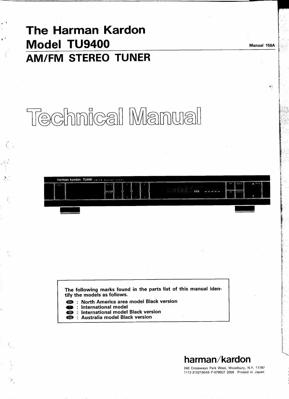
Harman kardon tu 9400 service manual

This is the 47 pages manual for harman kardon tu 9400 service manual.
Read or download the pdf for free. If you want to contribute, please mail your pdfs to info@audioservicemanuals.com.

Page: 1 / 47
left right
harman kardon tu 9400 service manual

Extracted text from harman kardon tu 9400 service manual (Ocr-read)


Page 1

The Harman Kardon _ ' ,
Model TU9400
AM/FM STEREO TUNER

T@@mfi@@l Mammal

harman kardon TUE-500 .M m

The following marks found in the parts list of this manual iden-
tify the models as follows.

: North America area model Black version
: International model

: International model Black version

: Australia model Black version

$59?

harman/kardon

240 Crossways Park West, Woodbury4 NY. 11797
1112v3152|56A9 P-079007 2000 Printed in Japan

Page 2

8
st
as
D
I-

CONTENTS

SPECIFICATIONS .................................................... 2
LEAKAGE TEST ---------- '-
CONTROLS & DISPLAYS~
DISASSEMBLY PROCEDURES -~
POWER CORD REPLACEMENT-r
ALIGNMENT PROCEDURES
CIRCUIT DESCRIPTION ------ ..
BLOCK DIAGRAM ....................................................... 7

2
..3
4

4

5

7

SPECIFICATIONS

OFM SECTION Nominal Limit
Tuning Range 87.5 ~ 108.0MHz
50dB Quieting Sensitivity

Stereo 37.2dBf é 41(48ldBf
Usable Sensitivity

Mono 11.7dBf é 15(17ldBf
Image Ratio 47dB g 40(7OIdB
IF Rejection 85dB g 75(80)dB
Spurious Response Rejection soda
Capture Ratio at 65dBf 1.2dB é 2dB
Alternate Channel Selectivity 40dB g 30(60ldB
AM Rejection 60dB ; 45dB
Signal to Noise Ratio

Mono 83dB ; 77(71ldB

Stereo 75dB g 69(63ldB

Total Harmonic Distortion
l65dBf 1kHz Input)
Mono 0.09% g 0.3%
Stereo 0.07% g 0.5%
Stereo Separation at 1kHz 58dE 2 40(35)dB

This figures in parenthesis l ) in the FM section are specifications for
the International model.

GENERAL UNIT

(EXPLODED VIEW, PARTS LIST) 8
WIRING DIAGRAM 10
RC. BOARDS-- 11
ELECTRICAL PARTS LIST 13
IC BLOCK DIAGRAM 17
IC TERMINAL FUNCTIONS 20
SCHEMATIC DIAGRAM-r - 23
0AM SECTION Nominal Limit

Tuning Range
North America area model
International and Australia

520 ~ 1,710kHz
531 ~ 1,802kHz

models
Usable Sensitivity 17/4Vm
Selectivity 58dB
Signal to Noise Ratio 53dB g 47dB
Image Rejection 40dB ; 30dB
IF Rejection 66dB ; 50dB

ODIMENSIONS (W x H x D) 17-3/8" x 2-7/8" x 13-1/ "
(442 x 73 x 342 mm)
OWEIGHT 7.5 lbs. (3.4 kg)
.POWER SUPPLY

North America area model

International and Australia

AC120V, GDHZ
ACZ20/240V, 50/60Hz

models

OPOWER CONSUMPTION
North America area model 12W
International and Australia 12W
models

These specifications are Service target specs.
Specifications and components subject to change without notice.
Overall performance will he maintained or improved.

LEAKAGE TEST (FOR SERVICE ENGINEERS IN THE U.S.A.)

Before returning the unit to the user, perform the following safety checks:

1. Inspect all lead dress to make certain
that leads are not pinched or that

SIMPSON MODEL 229 ETC, FOR

, LEAKAGE TEST
hardware Is not lodged between the
, . To EACH EXPOSED TO Ac GROUND SUCH
ChaSSIS and other metal Parts I" the METAL SURFACE OF As WATER on GAS PIPE.
unit. UNIT UNDER TEST HIGH GROUND ex CABLECONDUIT. ETCt
. . VOLTAGE LEAD
2. Replace all protective devrces such OH + LEAD

as nonmetallic control knobs, in-
sulating fishpapers, cabinet backs,
adjustment and compartment covers
or shields, isolation resistor-
capacitor networks, mechanical in-
sulators, etc.

3. Be sure that no shock hazard exists; check for leakage current
using Simpson Model 229 Leakage Tester, standard equipment
item No. 21641, RCA Model WT540A or use alternate method as

follows:

Plug the AC line cord directly into a 120-volt AC receptacle (do not
use an Isolation Transformer for this test). Using two clip leads,
connect a 1500 ohm, 10-watt resistor paralleled by a 0.15,uF
capacitor, in series with all exposed metal cabinet parts and a
known earth ground. such as a water pipe or conduit. Use a VTVM
or VOM with 1000 ohms per volt, or higher sensitivity to measure

é

VTVM
AC SCALE 0_


1.5KOHM
10W

TEST PROBE

TO EXPOSED
METAL PARTS

CONNECT T0 KNOWN
EARTH GROUND