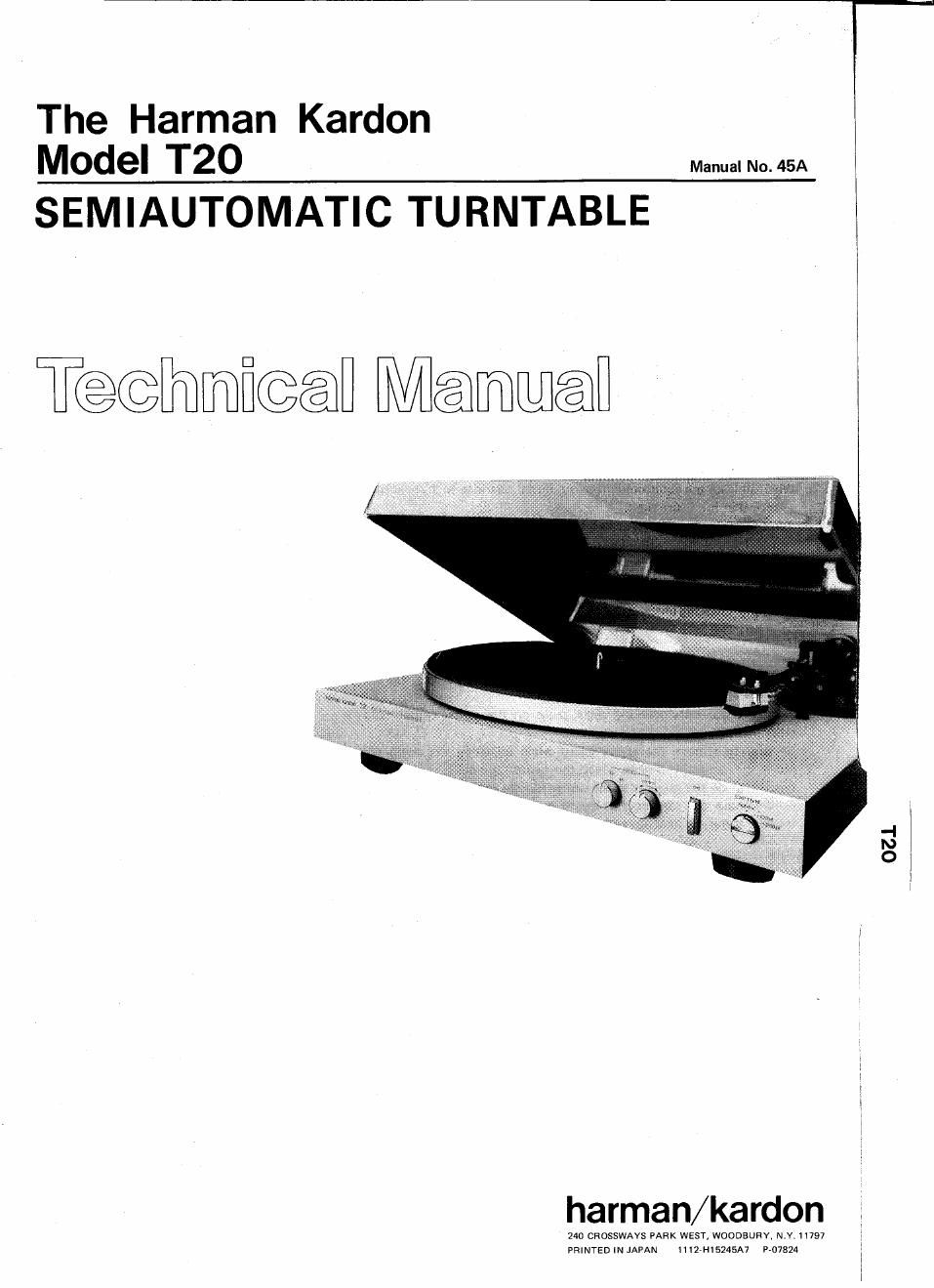
Harman kardon t 20 service manual

This is the 8 pages manual for harman kardon t 20 service manual.
Read or download the pdf for free. If you want to contribute, please mail your pdfs to info@audioservicemanuals.com.

Page: 1 / 8
left right
harman kardon t 20 service manual

Extracted text from harman kardon t 20 service manual (Ocr-read)


Page 1

The Harman Kardon
Model T20 Manua.No.45A

SEMIAUTOMATIC TURNTABLE

T@@mfi@@ Méamwén

harman/kardon

240 CROSSWAVS PARK WEST, WOODBUHY, N.Y 11797
PRINTED IN JAPAN HiZ-H15245A7 P-07324

OZJ.

Page 2

T T 'mi

SPECIFICATIONS
Nominal Limit
Speed Control Width Weight 11 lbs. (5 kg)
33-1/3 :3.0% Power Supply
45 i3-0% U.S. & Canadian Models AC 120V, 60Hz
Wow and Flutter 0.06% 30.09% Multi-Voltage Model AC 110-120V/220-240V
Signal-to-Nolse Ratio 260dB 50/60Hz
Possible Cartridge Weights 2.59 '\I 89 Power Consumption 3W
Dimensmns (W x H x Dl 153/16" X 5'1/ H x 14'3/16" Specifications and components subject to change without notice.
(368 X 134 X 360 mm) Overall performance will be maintained or improved.

CARTRIDGE REPLACEMENT

Only use cartridges in the headshell provided. Be sure to use a cartridge weighting 2.5 to 8 grams.
Retaining screw
\F Headshell
Washer-v%E I

1. Release the tonearm clamp and lift the tonearm gently.

2. Loosen the headshell clamp and gently pull the headshell with cartridge.

3. Disconnect the 4 leads from cartridge terminals using a tweezers and
then loosen the retaining screws so that the cartridge comes out.

4. Replace the leads onto the new cartridge. Refer to figure right for
correct placement of leads.

5. When all leads are connected properly, install cartridge to the headshell

Connecting leads

l l
53%;...

as shown in the figure right. %/ <\ '
l 6. Temporarily tighten the retaining screws to hold the cartridge. \ ii Cartridge &
7. Insert the headshell with the cartridge fully into the tonearm and then SW'US l M" Blue Green
tighten the headshell clamp. White 9 Left channel

Red -> Right channel

I
l . . . . . . Blue 9 Left channel ground
l When cartridge is replaced With new one. It is necessary to adjust the Green » Righlchannelgmund
l

l

Overhang and Tracking angle.


malnlng screws.

OVERHANG ADJUSTMENT a

1. Place the accessory tracking angle gauge on the center spindle and
erect the flap.
2. Be sure to remove the stylus guard when adjusting the overhang,
c) 3. Move the tonearm directly over the center spindle. Lift up the
raised flap on the gauge with the center spindle and the tonearm base.
Gently move the cartridge backward or forward in the headshell so
that the stylus tip lines up with the corner of the flap.

The flap should be
in the same straight
line as the axis of
the tonearm and as

l Slightly slacken the
7
2 the center spindle.


Move the cartridge backward
or forward so that the stylus
tip comes precisely over the
position indicated on theilap.

T20

TRACKING ANGLE ADJUSTMENT

. Check to be sure that the overhang adjustment has been completed.

2. Now move the tracking angle gauge until it is in the same position
with respect to the tonearm as that shown in Figure A. Place the
stylus over the tracking angle setting point with keeping stylus guard

Adjust the cartridge so that the
iron: or the cartridge is parallel
with the parallel lines.


attached. \ '
3. Without changing the stylus position, turn the cartridge so that its Ce
front edge is parallel with the lines on the gauge. Figure A Parallel

4. Now move it so that it is in the position shown in Figure B and check
that the cartridge is still parallel with the parallel lines as it was in step
3 above. If it is not parallel, then repeat step 3 and 4 alternately until
the cartridge is parallel in both cases.

5. When the above adjustment is completed, then tighten the screws that
attach the cartridge to the headshell fully.

parallel

Figure B