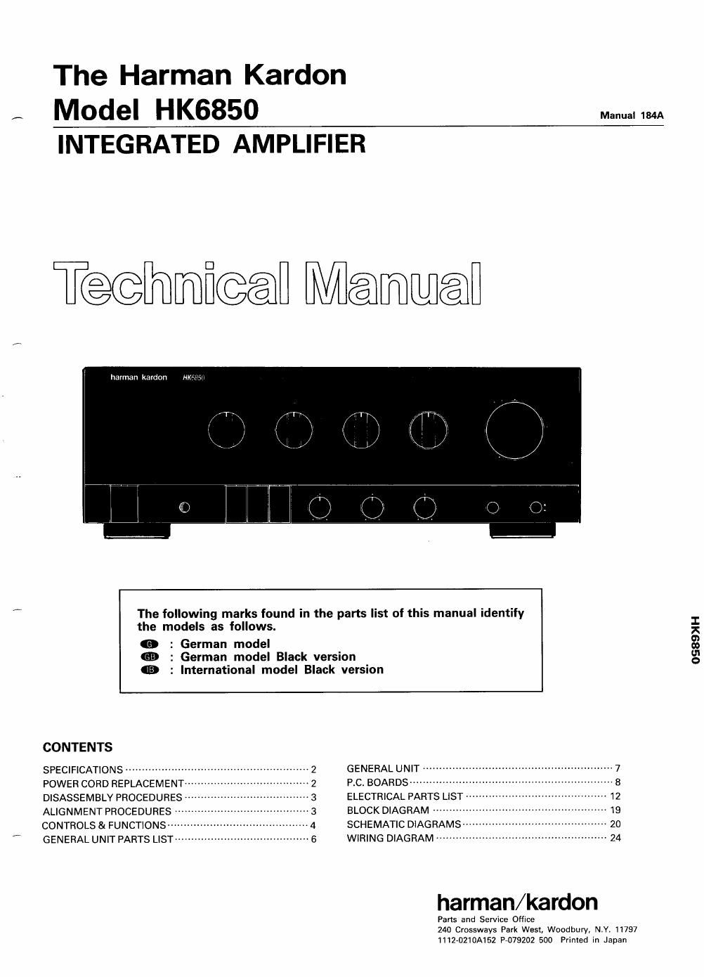
Harman kardon hk 6850 service manual

This is the 46 pages manual for harman kardon hk 6850 service manual.
Read or download the pdf for free. If you want to contribute, please mail your pdfs to info@audioservicemanuals.com.

Page: 1 / 46
left right
harman kardon hk 6850 service manual

Extracted text from harman kardon hk 6850 service manual (Ocr-read)


Page 1

The Harman Kardon
, Model HK6850 M 1m
INTEGRATED AMPLIFIER

T@@mfi@@ Ménmwéa

barman kardon

The following marks found in the parts list of this manual identify
the models as follows.

(E : German model
an : German model Black version
9 : International model Black version

CONTENTS
SPECIFICATIONS ------------------- 2 GENERAL UNIT 7
POWER CORD REPLACEMENT 2 P.C. BOARDS -------- 8
DISASSEMBLY PROCEDURES 3 ELECTRICAL PARTS LIST
ALIGNMENT PROCEDURES ----- 3 BLOCK DIAGRAM -------------
CONTROLS 81 FUNCTIONS ----- -- 4 SCHEMATIC DIAGRAMS

r GENERAL UNIT PARTS LISTW 6 WIRING DIAGRAM ------------

harman/kardon

Fans and Service Office
240 Crossways Park Wesl, Woodbury, N.Y, 11797
lilZ-OZIDAISZ P075202 500 Primed In Japan

0589)! H

Page 2

HK6850

SPECIFICATIONS
Nominal Limit Nominal Limit
Continuous Average Power (FTC) Tone Control Characteristics

20Hz-20kHz, both channels driven Bass (at 50Hz)

80, 0.08% RMS 97W 2 85W Boost 10dB i 2dB

40, 0.1% RMS 159W a 120W Cut 10dB i 2dB
High instantaneous Current Treble (at lOkHz)

Capability (HCC) 80A ; 60A Boost 10dB i 2dB
Half Power Bandwidth <10Hz~>100kHz <10Hz~70kHz CUt 10dB i 2dB
Frequency Response Filters

(at -3dB down) <1Hz ~ >110kHz Subsonic 15Hz, 3dB i 1dB/Octave
Square Wave Rise Time ZySeC § 2.5 [1 sec Phase Correct Loudness at 50Hz 6dB i 2dB
Input Sensitivity (at 85W output) DC Output Voltage

CD 135mV i 25mV L channel OmV i GOmV

Phono (MM) 2.2mV i 0.3mV R channel OmV i BOmV

Phono (MC) 130;:V i 20;)V RIAA Equalization at Tape Out
Signal to Noise Ratio (20Hz/20kHz) (10km load) 0.2dB i0.5dB

CD 78dB ; 70dB Phono Over load (No load)

Phono (MM) 77.6dB ; 75dB Phono (MM) 168mV ; 120mV

Phono (MC) 74dB g 67dB Phono (MC) 8.5mV g 5mV
Channel Separation (at 10kH2) Dimensions(Wx H xD) 17-3/ "x6~5/16" x15-15/16"

CD 46dB ; 40dB (443 X 160 x 405mm)

Phono (MM) 48.2dB g 40dB Weight 34le. Boz. (15.5kg)

Phono (MC) 49.6dB g 40dB Power Supply AC 230/240V, 50/60Hz
IM Distortion Ratio 0.039% g 0.1% Power Consumption 280W
Damping Factor at 1kHz 100 g 70

These specifications are service target specs,

Specifications and components subject to change without notice.
Overall performance will be maintained or improved.

POWER CORD REPLACEMENT

In order to prevent fire or shock hazard when replacing the power cord, follow the procedure below to replace the parts with
the standard supply parts.

COl
CONNECTOR

Pass the lead wires
through the holder
to fix.

and squeeze with a wrench (JST Ys-1614).
2. Cover the lead wires with the Special tube.

P1
POWER CORD CABINET BACK

USHING


T1 POWER
TRANSFORMER


Pinch the power cord with
the holder and fit the holv
der into the hole on the
cabinet. back.

SW1
VOLTAGE SELECTOR

BROWN LEAD

RED LEAD