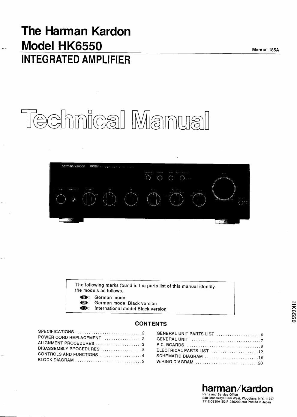
Harman kardon hk 6650 service manual

This is the 30 pages manual for harman kardon hk 6650 service manual.
Read or download the pdf for free. If you want to contribute, please mail your pdfs to info@audioservicemanuals.com.

Page: 1 / 30
left right
harman kardon hk 6650 service manual

Extracted text from harman kardon hk 6650 service manual (Ocr-read)


Page 2

SPECIFICATIONS

Nominal Limit
RMS Output Power

BI), lkHz THD 091% 56.5W250W

4Q. 1kHz THD 03% 83Wg70W
High-instantaneous Current

Capability (HCC) 37Ag32A

Half Power Bandwidth
Frequency Response
at -3dB

<10Hz~100kHz<10Hz~70kHz

0.4Hz~190kHz<1Hz~g150kHIG®

0.4Hz~200kHz<1Hz~g150kHZ®
input Sensitivity

Tuner, CD, Video 135mVi25mV
Phono (MM) 22mvtgg mV
Phono (MC) iZOuViZOuV
Signal to Noise Ratio
Tuner, CD, Video B1ng74dB
Phono (MM) aoeaysee
Phono (MC) 76ng70dB
Channel Separation at kaHz
CD 49ng45dB
Phono (MM) 52ng45dB
Phono (MC) 50ng43dB
lM Distortion Ratio 0,06%§O.1%
Damping Factor at 1kHz 69550
Tone Control Characteristics
Bass at 50H:
Boost 10$:de
Cut 10dBi2dB
Treble at 10kHz
Boost 10dBi2dB
Cut 10dBi2dB

POWER CORD REPLACEMENT

Nominal Limit

Filters

Subsonic at 15Hz -3dBi1.5dB

Phase Correct Loudness at SOHz GdBtsdB
DC Output Voltage

L channel OmViGOmV

R channel 0mVi60mV
RIAA Equalization at Tape Out

(20Hz/20kHz) 0,03dBt0.5dB/»0t15dBtO,5dB
Phono Overload THD 01%

Phone (MM) 115mvg100mv

Phono (MC) 6t1ng5mV

Dimensions (W x H x D) 17-1/2" x 5-1/4" x 14-3/16"
(443 x 134 x 359mm)

203 lbs. (9.2 kg)

AC 230/240V, 50/60HZ

220W

Weight
Power Supply
Power Consumption

These specifications are service target specs,

- Specifications and components subject to change without
notice. Overall performance will be maintained or improved

in order to prevent fire or shook hazard when replacing the power cord, follow the procedure below to replace the parts with the

standard supply partst

Pass the lead wires through
the holder to fix.

Pt
POWEFI CORD

SW101
VOLTAGE
SELECTOR

Pinch the power cord with
the holder and lit the holder
into the hole on the cabinet
backt
B USH ING

HOLD E R

Pass the lead wires through
the holder to fix

HOLDER
CABINET BACK

P.C. board and the lead wire (blue) of the

power cord together. and put the connector

on the wires and squeeze with a wrench (JST l

vs~1614t
2, Cover the lead wires with the special tube.

1. Twist the lead wire (red) of the power Switch]

CO1
CONNECTOR

T1
POWER
TRANSFORMER

tlomm