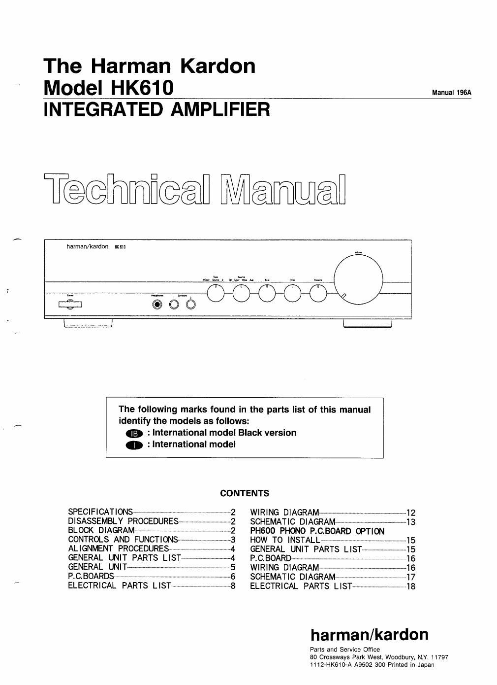
Harman kardon hk 610 service manual

This is the 22 pages manual for harman kardon hk 610 service manual.
Read or download the pdf for free. If you want to contribute, please mail your pdfs to info@audioservicemanuals.com.

Page: 1 / 22
left right
harman kardon hk 610 service manual

Extracted text from harman kardon hk 610 service manual (Ocr-read)


Page 1

The Harman Kardon
Model HK610 Mam
INTEGRATED AMPLIFIER

Tedfimiwl Meumwieii

harman/kardon mm

The following marks found in the parts list of this manual
identify the models as follows:

fig, : International model Black version

0 :International model

CONTENTS

SPECIFICATIONS ........................
DISASSEMBLY PROCEDURES
BLOCK DIAGRAM ------
CONTROLS AND FUN
ALIGNMENT PROCEDURES-w

WIRING DIAGRAM ..........
SCHEMATIC DIAGRAM-~-
PHSOO PHONO P.C.BOAR OPTION
HOW TO INSTALL -------------------------------

x

P.C.BOARD$ - - SCHEMATIC DIAGRAM--
ELECTRICAL PARTS LIST - ELECTRICAL PARTS LIST

harman/kardon

Paris and Service Office
80 Crossways Park West. Woodbury, NY. 11797
1112-HK610-A A9502 300 Printed in Japan

Page 2

HK610 :

SPECIFICATIONS
Nominal Limit Nominal Limit

RMS Output Power Damping Factor (at 1 Hz): 106 g 90

8 Q, 1kHz THD 0.1% 415W a 30W Phono-Overload

4 Q, IkHz THD 0.3% 57W a 45W Option Phono (MM): 109mV
High»instantaneous Current Option Phono (MC): 546mV

Capability (HCC) 34A ; 20A Tone Control Characteristics
Half Power Bandwidth (THD 0.1%) <1 OHZ73kHZ <1 DHz-SOkHz Bass (at 50Hz) Boost 10dB i 2dB
Frequency Response Cut 10dB i 2dB

(at ~3dB down) 0.4Hz-110kHz <1 Hz- ; 80kHz Treble (at 10kHz) Boost 10dB j: 2dB
Input Sensitivity Cut 10dB i 2dB

(at 30W output) Tuner/CD: 135mV >135mV i 35mV/17kQ : 5kQ DC Output Voltage (at 89)

Option Phono (MM): 2.4mV/49kohm L channel OmV i 60mv

Option Phono (MC): 131/4V/56K2 Fi channel OmV :I: 60mV
Signal to Noise Ratio Idling Current (at 8(2) 75mA j: 5mA

Tuner/CD: BBdB : 75dB Dimension 174" X 4.1 X 141'

Option Phono (MM): 79dB (W X H X D) (443 X 104 X 359 mm)

Option Phono (MC): 75dB Weight 14.3 lbs/6.5kg
Channel Separation (at 10kHz): 69:18 a 45GB Power Supply AC 230V, 50/60Hz

Option Phono (MM): 65dB Power Consumption 150W

Option Phono (MC): 65dB
IM Distortion Ratio (at 1W): 0.025% § 0.1% These specifications are sen/ice target specs.

Specifications and components are subject to change without notice.
Overall performance will be maintained or improved.

DISASSEMBLY PROCEDURES (REFER TO PAGES 5 ANDIZ)

CABINET TOP 131 REMOVAL 4. Disconnect the 1 connector (CW91) from 1 connector
iIi Remove 6 scre(ws ()A) and then remove the Cabinet (CN91) on the Main P'C' Board (PCB'U'
5. Remove 8 screws (D) and then remove the Chassis
Top(131). (161).
(El FRONT PANEL ASSY (AA) REMOVAL 6. Remove 11 screws (E) and then remove the Main PC.
1. Pull out 5 Rotary Knobs (151). Board (P034)-
2. Remove thEI Cabinet Top (131), referring to the pre- [Ii OPTION PHONO P.c. BOARD 0,0340 REMOVAL
vious step . , .
3. Remove 5 screws (B) and then remove the Front 1 223180;;Ehficmmet mp (13 referring to the pre-
Panel Assy (AA) 2. Remove 1 screw (199) and then disconnect 2 connec-
E] MAIN P,c, BOARD (PCB-1) REMOVAL tors (CW602 and W691) from 2 connectors (CN102
1 Remove the Front Panel Assy (AA), referring to the and CN101) 0" the Main P~C- Board (PCB-1)?
previous step El,
2. Remove the Rotary Knob (150) and remove the 2
Push Buttons (146),
3. Remove 6 hexagon nut (C) and then remove the VR
P.C. Board (PCB-9).
BLOCK DIAGRAM
BALANCE
SOURCE TAPE VOLUME
SELEETOR MONITOR EMS/TREE E
vrnso @--> vmeo
1/Cupy POWER
TUNER @--> rum -> Same D DOSPEAKERS
[ID MP
to @--> 2
AUX @-T-> W
F """ i
---------- EG
F AMP E
LPHONO (gr-J j
OPTION
m @-»-
TAPE 1
our @-<-----
IN (9"
TAPE 2
OUT @---<-