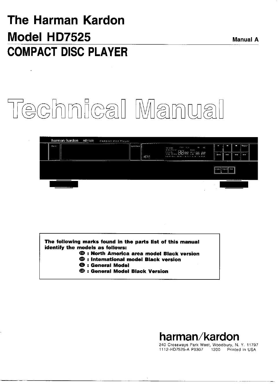
Harman kardon hd 7525 service manual

This is the 51 pages manual for harman kardon hd 7525 service manual.
Read or download the pdf for free. If you want to contribute, please mail your pdfs to info@audioservicemanuals.com.

Page: 1 / 51
left right
harman kardon hd 7525 service manual

Extracted text from harman kardon hd 7525 service manual (Ocr-read)


Page 1

The Harman Kardon

MOdel HD7525 ManualA
COMPACT DISC PLAYER

T@@mfi@@fl Mammfl

The following marks found in the parts list of this manual
identify the models as follows:
1% : North America area model Black version
® : lntemational model Black version
0 : General Model
® : General Model Black Version

harman/kardon

240 Crossways Park West, Woodbury, N. Y. 11797
1112-HD7525-A P9307 1200 Printed in USA

Page 2

HD7525

( CLAsst LASER mower Be careful of the Laser Pickup.
Produd mmplies Wm DHHS rules on: subchapter J pan Although you cannot see it from the outside, a laser
1040:10 at date of manufacture. pickup is located under the disc tray and a precision

is built in ' .
DANGER - invisible laser radiation when open and intertook tailed lens '1

ordefeabd- AV°id We emumm 9 beam Since the laser pickup, including the Iense element,
cAu-noN . use of 3 mm, adjustments 0, perfm d is especially sensitive to dust, keep the disc tray
procedures other than those specified herein may result in closed when not in use. Also do not put your hand
hazardous radiation exposure. inside the unit.

ADVARSEL:
Usynlig laserstraling ved abning nar sikkerhedsaibrydere er

ude at iunktion, Undga udsaettelse for straling.

CLASS 1

LASER PRODUCT

VAROlTUS!
Latte sisaiiaa laserdiodin. joka Iéhettaa' nakymatonta silmille
vaarallista Iasers'a'teiiyéi.
\ 1
CONTENTS
SPECIFICATIONS .............................. 1 CIRCUIT DESCRIPTION ........................ 19
SAFETY PRECAUTIONS ......................... 2 GENERAL UNIT (EXPLODED VIEW) .............. 23
AC LEAKAGE TEST ............................ 2 CD MECHANISM (EXPLODED VIEW) ............. 25
ELECTROSTATICALLY SENSITIVE DEVICES ....... 3 GENERAL PARTS LIST ......................... 26
CONTROLS AND FUNCTIONS ................... 4 CD MECHANISM PARTS LIST ................... 27
REMOTE CONTROL ............................ 5 ELECTRICAL PARTS LIST ...................... 28
DISASSEMBLY PROCEDURES ................... 6 IC DIAGRAMS ................................. 32
POWER CORD REPLACEMENT .................. 7 P. C. BOARDS ................................ 36
ADJUSTMENT PROCEDURE ..................... 8 WIRING DIAGRAM ............................. 38
TROUBLESHOOTING .......................... 10 SCHEMATIC DIAGRAM ......................... 39
IC FUNCTIONS ............................... 14
SPECIFICATIONS
Nominal Limit
System : Compact Disc Digital Audio
D/A Converter : Dual 18 Bit Linear D/A Converters, 4Fs Digital Filter, RLS
(ReaHime Linear Smoothing)
Signal Detection : S-Beam Semiconductor Optical Laser Pickup
Error Correction : CIRC System
Low Level Linearity : +/-1.0dB @-90dB
Frequency Response : OdB 0.5dB
(20HZ to 20kHz) *
Total Harmonic Distortion (THD) : 0.004% <0.008%
Dynamic Range : 96dB 290dB
Signal to Noise Ratio : 104dB 210MB
Channel Separation : 98dB 290dB
Line Output Level/Impedance : 2.0V 8.0V 0.5V @ 10k
Digital Output Level/Impedance : 0.5Vp-p 0.5thp 0.1Vp-p @75
Power Supply i 9
USA and Canada models : AC120v. 60Hz
International, Australia and
Asia/Oceania models : A0230/240V, 50/60Hz
Power Consumption : 20 Watts
Dimensions : 173/8" x 4 x 13"
443mm x 103mm x 326mm
Weight : 1 1 .5Ibs/5.2kg

Specifications and components subject to change without notice. Overall performance will be maintained or improved.

1