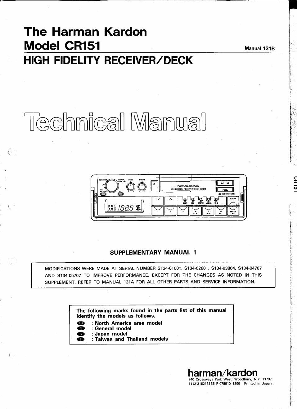
Harman kardon cr 151 service manual 2

This is the 20 pages manual for harman kardon cr 151 service manual 2.
Read or download the pdf for free. If you want to contribute, please mail your pdfs to info@audioservicemanuals.com.

Page: 1 / 20
left right
harman kardon cr 151 service manual 2

Extracted text from harman kardon cr 151 service manual 2 (Ocr-read)


Page 1

-l

The Harman Kardon
MOdel CR151 Manual 1313
HIGH FIDELITY RECEIVER/ DECK

T@@Ih][mfi@@fl Mammal

mm _'
men mam mmmnacx ems! m]

on upturn»:

C
I
-l
U
a

SUPPLEMENTARY MANUAL 1

MODIFICATIONS WERE MADE AT SERIAL NUMBER 3134-01001, 8134-02601, 3134-03804, 3134-04707
AND 5134-05707 TO IMPROVE PERFORMANCE. EXCEPT FOR THE CHANGES AS NOTED IN THIS
SUPPLEMENT, REFER TO MANUAL 131A FOR ALL OTHER PARTS AND SERVICE INFORMATION.

The following marks found in the parts list of this manual
identify the models as follows.

on : North America area model
0 : General model

0 : Japan model

0 :Taiwan and Thailand models

harman/kardon

240 Crossways Park West, _Woodbury, N.Y. 11797
1112615213155 P078810 1200 Printed in Japan

wmfi -y-"'::,-v Hm WWW

Page 2

-
In
F
D:
O

SPECIFICATIONS

[for General, Taiwan and Thailand models] [for Japan model]

OFM SECTION Nominal Limit OFM SECTION Nominal Limit
Tuning Range 87.5MHz ~ 108.0MHz Tuning Range 76.1MH2 ~ 89.9MHz
Signal to Noise Ratio IF Rejection (82.0MHz) 83dB g 75dB

Mono 74dB a GOdB Image Rejection (82.0MHzi 57dB g 50dB
IF Rejection (90.0MHz) 83dB ; 75dB
Image Rejection (98.0MH2) 57dB ; 50dB 0AM SECTION
Output Level (75kHz dev.) 775mv i adB Tuning Range 522kHz ~ 1629kHz

0AM SECTION
Tuning Range 531kHz ~ 1602kHz

ALIGNMENT PROCEDURES

I ELECTRICAL ADJUSTMENT
4. Standard load


FM Signal Generator 1kHz, 100% modulation

1kHz, 45% modulation

Stereo Modulator L+R=45.5%, L-R=45.5%, 19kHz=9%

L+R=22.5%, L-R=22.5%. 19kHz=8%

I TUNER SECTION [for Japan model]


OConnect the FM Signal Gener- 82.0MHz

82.0MHz

T601 Maximum output
ator to the Antenna jack (17dBf)
through the FM dummy
antenna. 82.0MHz 82.0MHz VR601 Minimum distortion
0Connect Oscilloscope, Distor- (65dBf)
tion Meter and AC Voltmeter
IF to the line output. FM
82.0MHz 82.0MHz T601 Connect the digital Volt-
(65dBf) meterto TP1 and TP2 on
PCB-4. Adjust so that the
reading of the digital
Voltmeter is oi25mv.
, I Sub-Carrier OCOnnect the Stereo Modula- FM 82.0MHz 82.0MHz VR604 Minimum output at
» rejection tor to FM Signal Generator. Stereo (65dBf) 19kHz pilot signal only
Connect the FM Signal Gener- by Stereo Modulator
ator to the Antenna jack
through the FM dummy 82.0MHz 82.0MHz Adjust so that the right
antenna. (71dBf) channel output becom-
OConnect Oscilloscope, Distor- VR603 as minimum when only
tion Meter and AC Voltmeter the left channel of the
to the line output. Stereo Modulator is
Separation FM modulated
Stereo
Adjust so that the left
channel output becom-
VR603 es minimum when only
the right channel of the
Stereo Modulator is
modulated.
82.0MHz 82.0MHz VFISOZ Adjust so that the
(51dBf) Separation becomes

30d B

Repeat Step 5.

Repeat Step 6 for optimum separation.

(7
K