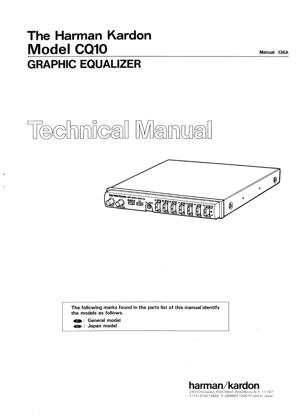
Harman kardon cq 10 service manual

This is the 9 pages manual for harman kardon cq 10 service manual.
Read or download the pdf for free. If you want to contribute, please mail your pdfs to info@audioservicemanuals.com.

Page: 1 / 9
left right
harman kardon cq 10 service manual

Extracted text from harman kardon cq 10 service manual (Ocr-read)


Page 2

SPECIFICATIONS

Frequency Bands : 7

Center Frequencies : 50Hz, 200Hz, 500H2, 1kHz,
3I2kHz, 8kHz, 16kHZ

: :10dB

: 0.1 -1.0V/30k Ohms

: 0.171.0V/10k Ohms

: 80Hz, 125HZ, 200Hz,
12dB/Octave

Boost/Cut Range

Input Sensitivity/Impedance
Output Level/Load
Subwoofer LowAPass Filter

Dimensions (W x H xD) :7-1/8 x1" x 5-7/8

(180x25x 149 mm)

Chassis Dimensions : 7" x1 x 5-1/8
(WxHxD) (178x25x130mm)
Weight : 1.5lbs. (0.7kg)

Specifications and components subject to change without notice
Overall performance will be maintained or improved.

DISASSEMBLY PROCEDURES (REFER TO PAGES 3 AND 8)

E) CABINET TOP (119) REMOVAL
Remove 4 screws (A) and then remove the Cabinet
Top (119).

Q FRONT PANEL (122) REMOVAL

1. Remove the Cabinet Top (119), referring to the previous
step )1].

2. Pull out the equalizer level knob (128)

3 Remove 2 screws (B) and then remove the Front Panel
(122).

BLOCK DIAGRAM

SW)
CD

INPUTMD

7*BAND
GRAPHIC EQUALIZER

CD INPUT

CD INPUT /L__o_. m

HHH?

-I-IEIE

(F
LOW PASS
°\°TO FILTER

E) MAIN P. C. BOARD (PCB-1) REMOVAL

1. Remove the Cabinet Top (119) and Front Panel (122),
referring to the previous steps )1) and )2).

2. Remove 2 screws (C) and then remove the Cabinet
Bottom assy (AA) and then remove the Knob (130).

3. Remove 4 connectors on the Main P. C. Board (PCBeII
and then disconnect lead wires.

4. Remove 4 screws (D) and then remove the Main P. C
Board (PCB-1).

5. Remove the attached a Nuts from VR201/302,
VR401/402.

E CONTROL P. C. BOARD (PCB-2) REMOVAL

1. Remove the Cabinet Top (119) and Front Panel (122),
referring to the previous steps m and IE.

2. Remove 4 connectors on the Main P. C. Board (PCBJ)
and then disconnect lead wires.

3. Remove 1 screw (E) and then remove the Control P. C.
Board (PCB-2).

o
I w;
mcxr
<-Io
mg:
r_,-I

BUFFER

SW2
EQ DEFEAT FADER

? FRONT PREOUT

we) I-vrv-I

?REAR PREOUT
BUFFER REF

OUTPUT

LEVEL

MUTINGI;
SW4

SUE WOOFER
HIGH LIMIT SUHLg'VOEOLFER

W SUB PREOUT

2UlJ/l 25/80)):