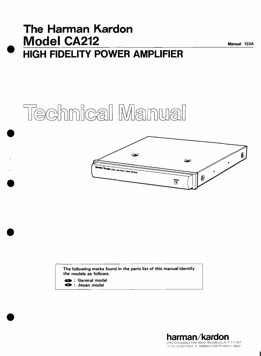
Harman kardon ca 212

This is the 8 pages manual for harman kardon ca 212.
Read or download the pdf for free. If you want to contribute, please mail your pdfs to info@audioservicemanuals.com.

Page: 1 / 8
left right
harman kardon ca 212

Extracted text from harman kardon ca 212 (Ocr-read)


Page 1

The Harman Kardon

MOdel CA212 ' Manual 133A
HIGH FIDELITY POWER AMPLIFIER

Tedmmfiwfl 11%]me

The following marks found in the parts list of this manual identify
the models as follows.

a : General model
0 : Japan model

harman/kardon

24000 ossways Pa rekW LOW Oudb mdeY11797
11213152133A POEBEOEIZOOPW HBJVH

Page 2

CA212

SPECIFICATIONS
Power Supply : DC +13.8V (1 1 ~ 16V usable),
Power Output, RMS : 12 watts per channel into . negative ground
4 Ohms, 20~2o,000Hz Tvplca} Input Current
HCC (High instantaneous : 5A Reqwrements
Current Capability) At Idle _ : 0.3A .
THD 5 No more than 1% Full Power Musrc Signal : 1.2A (4 Ohms/ch.)
(4 Ohms) Full Power Sine Wave : 3.6A (4 Ohms/ch.)
Negative Feedback ; 35dB Dimensions (W x H x D) : 7-1/8 x1 x 5-7/8
Power Bandwidth : 10Hz to 30,000Hz _ (180x 25x 149 mm)
Frequency Response : 10Hz to 100,000Hz Weigh} , I 2|bs. (03kg)
+0, -3d3 Chassrs DimenSIons : 7" x1" x 5-1/8
Signal-to Noise Ratio : 84dB (W X H X DI (178 X 25 X 130 mm)
Input Sensitivity/Impedance : O.1V/O.5V (SwitchableI/
22k Ohms
Specifications and components subject to change without notice.
Overall performance will be maintained or improved.
DISASSEMBLY PROCEDURES (REFER TO PAGES 3 AND 7) .
IE CABINET TOP (119) REMOVAL (E MAIN P. c. BOARD (PCB-1) REMOVAL
Remove 6 screws (A) and then remove the Cabinet 1. Remove the Cabinet Top (119), referring to the previous
Top (119L step m.
2. Remove 7 screws (C) and remove 2 screws (D). then
12 FRONT PANEL ASS'Y IAB) REMOVAL remove the Main P. C. Board (PCB-1L
1. Remove the Cabinet Top (119), referring to the previous
step E].

2. Remove 2 screws (B) and then remove the Front Panel

Ass'v (AB). .

BLOCK DIAGRAM

-o .
L? POWER AMP : L

>- -o
:
E">
INPUT E2; SPEAKER SYSTEM
WE; +
5 POWER AMP ° . R
RC? m -0,
REMOTE
MUTING CIRCUIT -0 REMOTE

4, |

+5 POWER -O+B

SUPPLY
r0 GND