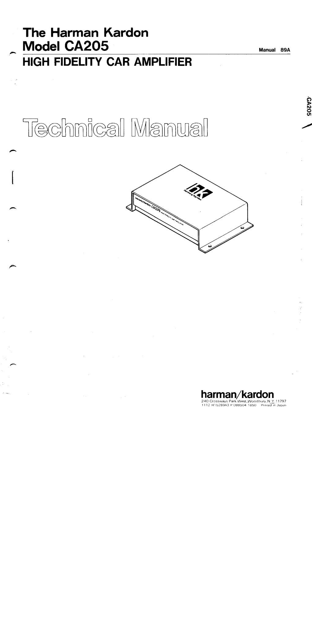
Harman kardon ca 205

This is the 6 pages manual for harman kardon ca 205.
Read or download the pdf for free. If you want to contribute, please mail your pdfs to info@audioservicemanuals.com.

Page: 1 / 6
left right
harman kardon ca 205

Extracted text from harman kardon ca 205 (Ocr-read)


Page 1

The Harman Kardon
f MOdel CA205 Manual 89A

HIGH FIDELITY CAR AMPLIFIER

\ SOZVO

T@@mfi@@fl Mama

harman/kardon
240 Crossways ParKWem,Wonchury,Nvi 1 1797
H IZ H15783A3 V 085304 H556 Prmsd m Jupnn

Page 2

CA205

SPECIFICATIONS

Power Output. RMS

Hcc (High Instantaneous
Current Capability)

THD (4 ohms)

Negative Feedback

Power Bandwidth

Frequency Response

Signal»to«Noise Ratio

Input Sensitivity/Impedance ;
: DC +13.8V (11~16V

Power Supply

: 3.5 watts per channel

into 4 Ohms,
20 ~ 20,000Hz
2 5A

: No more that 0.2%
: 25dB

: IOHz to 100,000Hz
: 10Hz to 100,000Hz

+0. -3dB

: QOdB

0.1V/22k Ohms

Typical Input Current
Requirements
At Idle : 0.2A

Full Power Music Signal:
Full Power Sine Wave
Dimensions (W x H x D)

Weight

0.4A (4 Ohms/ch.)

: 1.2A (4 Ohms/ch.)
: 6-3/4X 171/2 X4»1/8"

(172x38x105 mm)

: llbs. 502. (0.6kgi

Specifications and components subject. to change Without notice,
Overall performance Will be maintained or improved,

usable), negative ground

ALIGNMENT PROCEDURES

I Idling current adjustment

Conditions:

0 Connect a 13.8V power supply to the Power Supply
Lead.

0 After the power on, wait for 15 minutes before
measuring to be sure of the most stable operation.
0 Connect the DC voltmeter between TP1 and TP2 and

between TP3 and TP4.

Inspection:

0 Check that the voltage is between SmV and 30mV.
If it is higher than the specified range, adjust it accord
ing to the procedure described at the right.

DISASSEMBLY PROCEDURES

El CABINET TOP (131) REMOVAL
Remove 4 screws 6 and remove the Cabinet Top (131).

Adjustment:
Note: When disconnecting a resistor. disconnect the
power supply first.

Voltage Procedure

30mV ~ 53mV Cut out R135 and R136.

54mV ~ 77mV Cut out R137 and R138.

After the adjustment is complete, let the unit settle
down for 15 minutes. then double-check that the idling
current is set properly.

El MAIN P.C.BOARD REMOVAL

1. Remove the Cabinet Top (131). (Refer to step Ill.)

2. Remove 4 screws til and Loosen screw 0, then
remove the Main P.C.Board with Insulator (138).