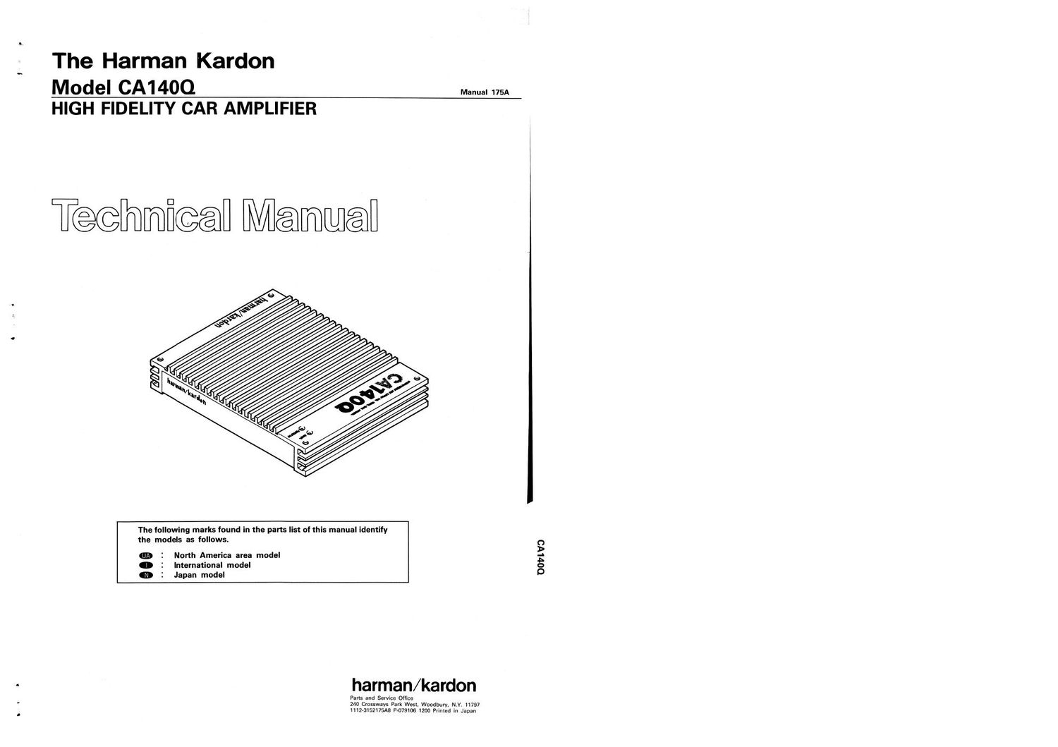
Harman kardon ca 140 q

This is the 10 pages manual for harman kardon ca 140 q.
Read or download the pdf for free. If you want to contribute, please mail your pdfs to info@audioservicemanuals.com.

Page: 1 / 10
left right
harman kardon ca 140 q

Extracted text from harman kardon ca 140 q (Ocr-read)


Page 1

The Harman Kardon

Model CA14OQ Mam. 175A
HIGH FIDELITY CAR AMPLIFIER

T@@mfi@@fl Memmenfl

The following marks found in the parts list of this manual identify
the models as follows.

m I North America area model
0 2 International model
0 2 Japan model

harman/kardon

O s w y Park Wesl, Woodbury, N. 797
1112-3152175 P7079106 1200 Printed in Japan

007 l V3

Page 2

CA1 400.

CA1400.

SPECIFICATIONS
Number of Channels : 4
Continuous Average : 35 Watts @ <0.1% THD into
Power per Channel, 4 Ohms
All Channels Driven 35 Watts @ <0.3% THD into
from 20Hz 7 20kHz 2 Ohms
70 Watts @ <0.3% THD
bridged into 4 Ohms
HCC : i30 Amps
Frequency Response : SHz-lOOkHz (+0, -3dB)
Signal-to-Noise Ratio : 100dB

JACKS, TERMINALS AND CONTROLS

Input Sensitivity/Impedance : 250mV/22kn (variable)
Power Supply : DC+14.4V (11-16V usable),
negative ground
: 2.25" x 12.6" x 94"
(57 x 320 x 240 mm)
Weight : 9 lbs. 1 02 (41 kg)

Dimensions (H x W x D)

All specifications and features subject to change without notice.

0 Power input terminals

0 2mm switch "' E

For... ,. . m «1 mm

6 e 8 8.

Lac-m} 5...... ,

eeee 6.6.66

,.. -l.

in.) 1 input r

9 Speaker terminals

0 50 Hz boost control
9 Input level control

(9 Input iacks

CONNECTIONS

General

Caution1: The ignition key switch should be turned off
before any connections are made to the car
electrical system.

Caution 2: Use a flat-bladed screwdriver with a blade width
of less than 5 mm to connect the cables Using a
screwdriver with a blade width of more than 5
mm can damage the screw slot.

Caution 3: The last connection to be made should be to the
positive terminal of the car battery.

Caution 4: Do not connect any of the CA14OQ speaker
terminals to the car chassis or to a common
ground Also, do not connect the speaker termin-
als of the CA14OO to the input terminals of
another amplifier or signal processor.

Connect the CAMOO to the car electrical system and to the

other components in the audio system as per the following

instructions:

Remote

This terminal enables the power switch of the car turner/CD
or turner/deck to also turn on the CA14OQ, Connect one end
of the accessory yellow cord to the appropriate lead lpower
amplifier remote) on the car turner/CD or turner/deck and the
other end to the remote terminal on the CA1400.

If a specific wire for this purpose is not provided on the
turner/deck, use the wire for controlling the power antenna. If
that wire is already connected to the power antenna, the
CA14OQ can be connected in addition.

+3

The +B terminal is the positive power input terminal. It
should be connected to the positive l+) terminal of the car
battery using the accessory red cord. The cord should be
installed such that the attached fuse holder is located near the
car battery.

GND

This is the negative power input terminal. It should be
connected directly to the car chassis using the accessory
black cord. It is not necessary to connect this terminal to the
negative battery terminal.

Input Jacks

These input jacks are for connection to the line (preamplifier)
output jacks on the car stereo or turner/deck. If is recom-
mended that high quality shielded coaxial cables with
tight»fitting FICA plugs be used for this connection.

lfthe car in-dash unit has a built-in power amplifier and does
not have line (preamplifier) output jacks, connect the speaker
wires to these input jacks Male phono plugs (not provided)
are required. lfthe built-in amplifier is the "High Power" type
(rated 12 watts per channel or more), a power»line adaptor
(not provided) must be used.

Adjusting Input Level and 50 Hz Boost Controls

Input level - This continuously variable control allows the
amplifier's sensitivity to be matched to the output level of the
in-dash unit. Initially, set this control to a low position, Turn
on the car audio system and attempt to play it at a
comfortable listening level. If the volume control on the
in-dash unit cannot increase the level sufficiently, increase
the input level control setting accordingly.

50 Hz boost -- This continuously variable control can add up
to 12 dB of boost to low frequencies in the 50 Hz range. This
can be used to compensate for the poor low frequency
response from some car speaker systems Set the bass and
treble controls on the in-dash unit to their center positions.
Defeat or bypass an equalizer, if used. While the car audio
system is playing at a comfortable listening level, increase
the setting of the 50 Hz boost control until the desired low
frequency effect is achieved.