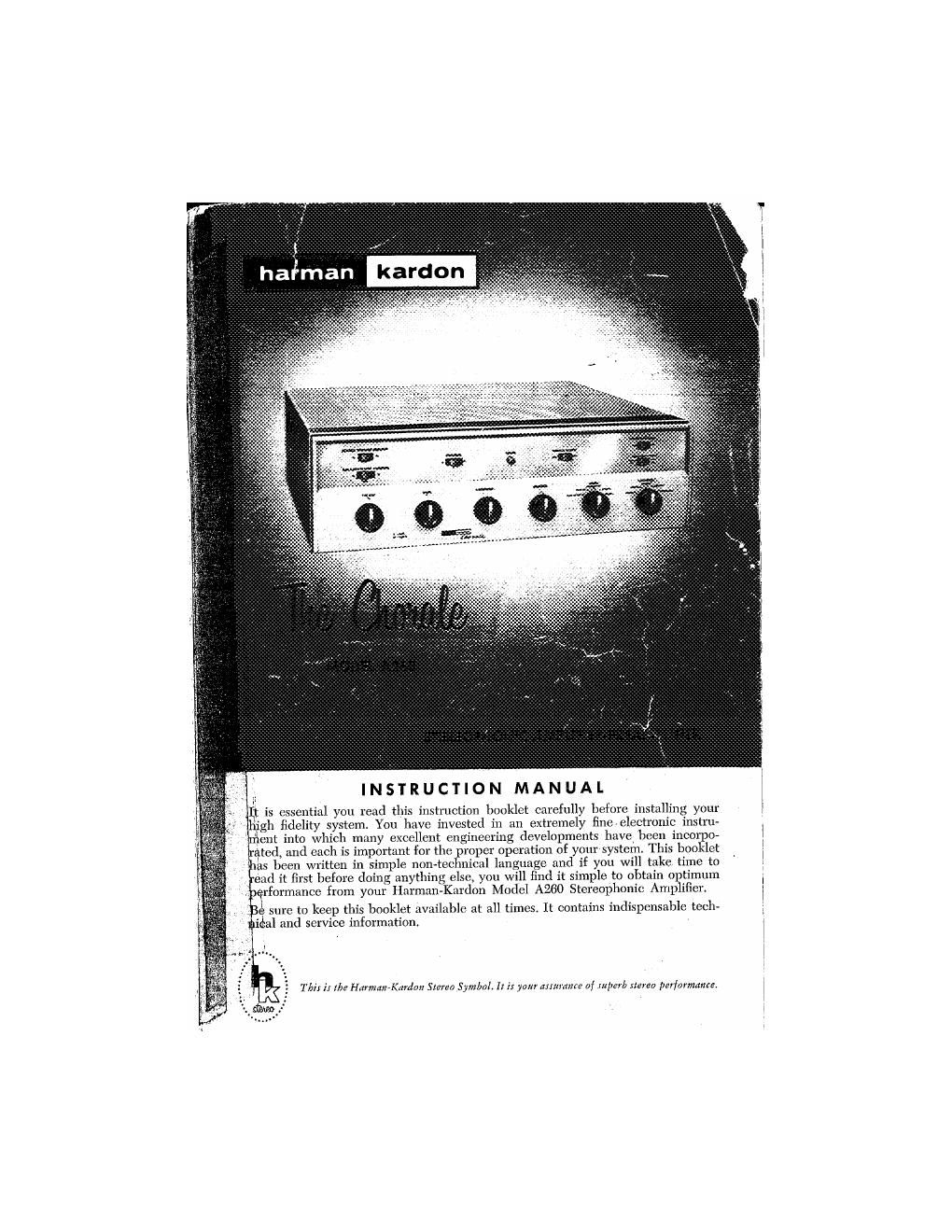
Harman kardon a 260 owners manual

This is the 7 pages manual for harman kardon a 260 owners manual.
Read or download the pdf for free. If you want to contribute, please mail your pdfs to info@audioservicemanuals.com.

Page: 1 / 7
left right
harman kardon a 260 owners manual

Extracted text from harman kardon a 260 owners manual (Ocr-read)


Page 1

INSTRUCTION MANUAL
It is essential you read this instruction booklet carefully before installing your
gh fidelity system. You have invested in an extremely lineelcctmnic instru»
. ent into which many excellent engineering developments have been incorpo-
: (lied, and each is important for the proper operation of your system. This booklet
! as been written in simple non-technical language and if you will take time to
, ead it first before doing anything else, you will find it simple to obtain optimum
V-erformance from your Haiman-Kardon Model A260 Stereophonic Amplifier.

i: sure to keep this booklet available at all times, It contains indispensable tech-
'¢lal and service information. .

Th}; 1'; [[79 Hmmqn-Kanion Stem Symbol. It i: yam anmuflre of JllpéYb Iterea par/ommne.

Page 2

UNPACKING

After unpacking the Chorale, inspect it carefully for signs of transit damage.
The unit was subjected to many inspections and tests prior to final packing, and
therefore should be in perfect condition If damage is visible, notify your
dealer at once. If the unit was shipped to you, notify the transportation company
without delay.

Check the contents of the carton thoroughly and inspect the folds of the
packing material before discarding it. Your package should contain the following
items:

1 Chorale, Model A260 Stereophonic Amplifier-Preamplifier.

1 Instruction Booklet.

1 Warranty Card.

1 Mounting Template.

v

WARRANTY POLICY

We urge you to fill in your warranty card and mail it to the factory without
delay to protect your rights under warranty. The warranty cards are carefully
filed for reference and should you require information on the use of this high
fidelity unit, or repair service, we will be able to identify your set and reply
quic y.

NOTE: It is necessary to receive factory authorization before returning a
set for warranty repair either to the factory or to an authorized station. Repairs
are to be returned on an Express Prepaid basis. A letter describing the exact diffi-
culty must be enclosed with the unit.

WARRANTY
We warrant each Model A260 to be free from defects in material and work-
manship under normal use and service, and in accordance with the conditions
herein below set forth, for a period of 1 year from date of delivery to the original
purchaser, and agree to replace or repair any part or parts, with the exception
of tubes which are under the manufacturers 90 days warranty, returned to us
within said I year, with transportation prepaid and which our examination shall
disclose to our satisfaction to have been thus defective. This warranty does not
include free labor, nor is it applicable to any instrument which shall have been
repaired or altered in any way so as in our judgment to affect its stability or
reliability nor which has been subject to neglect, misuse, abuse, negligence or
accident nor which has had the serial number altered, efiaced, or removed.
Neither shall this warranty apply to any instrument which has been connected
otherwise than in accordance with instructions furnished by us
This warranty is expressly in lieu of all other warranties, express or implied,
and of all other obligations or liability on our part, and we neither assume nor
authorize any representative or other person to assume for us any other liability
in connection with the sale of this instrument

INSTALLATION PROCEDURE

Ventilation:

The unit is well ventilated in itself, but sufficient space must be allowed
around it to permit proper air flow. Install the amplifier in a manner to allow for
unrestricted circulation. Do not place books or other objects on the cage or in
the immediate vicinity of the instrument. Reducing the air flow will result in
sharply reduced component and tube life. Allow at least 4 inches above the unit
for cabinet installation.

3m :MnMMtL

,,, .© Mum

© © '55}

|@ © IIIXI

@ @J nnxz

I-l
. (9" @ W Main;

,3 2 "W" , manners... .. massacre...

18 {.3 m... A... w,

k L , my in CHASSISI

may" shirts;

l [jiggaggo

. W5 mm "mun
c i . taugtnlllu . ml or .W 100w

DD J

m-m mm

Power Requiremenl:

Plug the AC cord into any outlet furnishing 117 volts 50 or 60 cycle AC cur
rent. The Voltage may vary between 105 and 125 volts. Two AC convenience
outlets are located on the rear panel of the instrument. Auxiliary equipment (tape
deck, record player, additional amplifier) may be plugged into these outlets and
will be controlled by the illuminated push»button on/oif switch on the front panel.

Connecting Your Speakers:

Your two speakers should be matched if possible to obtain optimum results
and should be placed approximately 8 to 15 feet apart against one wall of your
listening room. Corner placement is also quite acceptable. Facing the speakers
straight out or slanting them slightly will depend on your room size, acoustic
effect and where you will be seated for listening. It may be necessary to experi-
ment with speaker placement until best rcsults are obtained

Use any type wire to connect your speakers. Lamp cord is excellent and may
be easily dressed around the molding for an inconspicuous and neat installation.

The unique switching arrangement on the Model A260 enables you to con»
meet your speakers in any of several ways. Follow the diagrams listed below for
the installation best suited for your use.

Stereo In Room A. No Speakers In Room B:

Connect both leads from the left speaker in Room A to terminals A and
COM on the LEFT SPEAKER OUTPUT strip. Connect both leads from the
'i' lli speaker in Room A to terminals A and COM on the RIGHT SPEAKER

lTPUT strip. The shorting bars between all terminals on the SPEAKER
TPUT strips must remain connected for this method of operation. Refer to

gram 1,

The IMPEDANCE SELECTOR switches located on the rear of the chassis

d be placed in the 4, 8 or 16 ohm position depending upon the nominal imr
jed ce rating of your speakers,

'i o operate, the CENTER SPEAKER and the STEREO SPEAKER SELECT-
OR switches located on the front panel may remain in any position since they
are inoperative in this application.