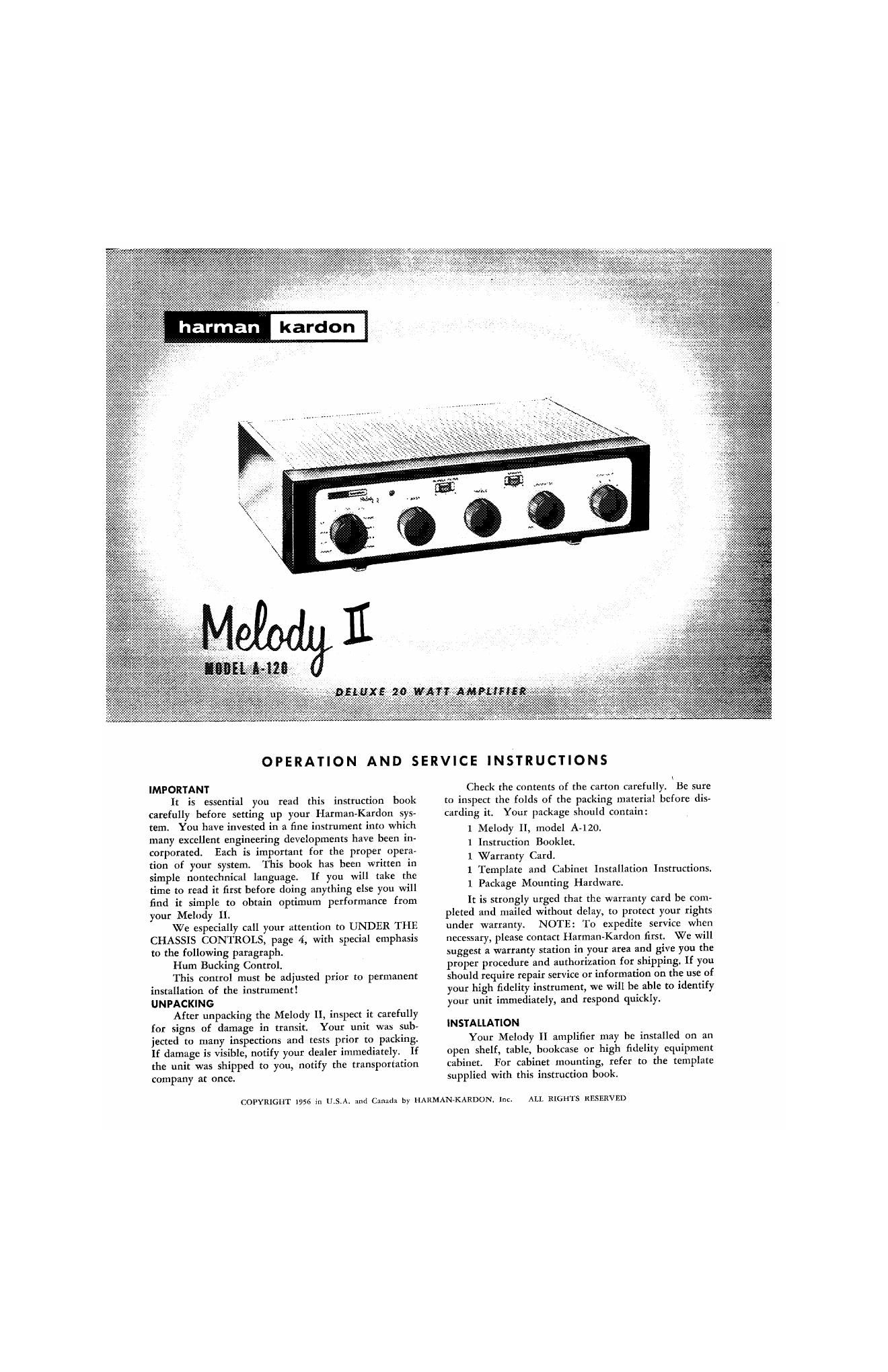
Harman kardon a 120 owners manual

This is the 6 pages manual for harman kardon a 120 owners manual.
Read or download the pdf for free. If you want to contribute, please mail your pdfs to info@audioservicemanuals.com.

Page: 1 / 6
left right
harman kardon a 120 owners manual

Extracted text from harman kardon a 120 owners manual (Ocr-read)


Page 2

Ventilation

All electrical equipment generates heat which mutt
he allowed to «cape. Althoudt the Melody ll it well
ventilated in hull. sullident spice should he allowed
around it to permit free air flow. I! it is placed in a
bookcase. it should he louted well toward the front. to

as much clearance u poaaihle at the rear. DO
NOT place hook: or other object on top of the Melody
ll. Covering the performed metal (age will prevent
proper air flow and will result in sharply reduced oom-
pom: and (tube life.
rm comm

Plug the AC ptmr cord into any outlet furnishing
"7 volts. so or 60 let hwse current. The exact
voltage is relatively unimportant and may vary between
105 and 125 volts, lle note, however, that you have a
SOorSOcycleACpnwernnu-oe. 'l'hehlelodyll has
several AC convenience outlets on the bottom of the
drastic. The proper one 0! there outlets ll described in
the section under Electrical Gmeotlona.
mlul CONNICI'DONS

Phonn'r-h Camelot»:

Any type oi retard player will operate with the
Melody II. To derive maximum enjoyment it is tug-
gaated that a my. quality pickup and a rumble-free tum
cahlehenaed. Twclasmul phpidtupsare
in use todty: Magnetic (GE. Audak, ESL, Pahchild,
Pickering and Retoron) and Crystal (including the
newly developed ceramics).

All magnetic car thould he crammed to the
PHONO jack on the sloped terminal panel on the
hotunnoftheunlt. Connecteryrtalnreer-amicem-
ridget to either iat'lt marked "AUX" also located on the
sloped terminal panel.

Whenualnga iecartridseitianmarym
slide the Pickup Selector Switch located on the bottom
panel near the "Pinon" input jack to the apptopeiate
podtinn. This switch ll mallard "all. and "Pi-it
(Pldtetlng). but an accommodate all Magnetic Cart-
ridges. Have the slide switch to the "(SJ-1." position for
all low level magnetic cartridgu ruch as General llloc-
uic. ESL and Fairdtild and to the "Pick position for
all hifit level magnetic «midget as Pickering Ind
And-It.

Awotkolodvioe: Thepnrchaseoladiamond
needle n a worthwhile invutment it has extremely
lnnglileandwillnntonlyprouetyourtecordshut
will insure maximum tone quality.

ltiannnetimesadvlaahletogmundthephonognph
drusirwthereoriverinmderurreduoehumand
other unwanted noise. Attach a wire to the metal
framework of the and com the other end
to the "6" terminal n! the Speaker Terminal Strip.

firepowercnrdultheremrddtansaorturntahle
may he played into either AC eonvenlenoe outlet lo-
canedonthnhomomoftheflelody ll.

Auxiliary Inputs:

The Melody ll ram two "AUX" inputs
loatedonthealoped hottompanelllngallhigh level
equipment. such as a tape recorder or television nrner,
intneitheriaclt. lfyonateuaingaceutnlcucryttal
phono cartridge make certain to connect your phono-
graph to the "AUX" jack. This podtion is tomrolled
hydsel-unctionSelecmrSwitehonthefrontpanel.

Inp- Input:

This innit is located on the bottom ul the Melody ll
chassis near the "Phnm" input inch. The amplifier ia
packed with a shorting plug inserted into this iadt which
am or a "unrting' switch to reduce hunt and switching
units when the selector switch is thrown. This shorting
plug should he removed when (tunneling a tape retorder

Program material from a tape retottler or tape
dork may be contracted into the Melody ll in two dilier-
entways. Uthetapemechaniamhnapreamplifieror
amplifier stage. it should he mooted to the AUX"
jack. If the tape meehaniam does not have a preampli-
fier, or if the amplifier it not of top quality. the tape head
may he outrun-ted to the "TAPE lNPU'l" jadt. Setting
the Function Selector Switch at the polltion marked with
the appropriate speed (3.75. 7.5 or 15) will then pro-
vide the equalization retouunended by the manufacturers
of pre-retorded tape.

7-w- W .

A root-[uncle melted TAPE OU'l'" is located on
the Melody ll MI. This is used to provide output to
a tape recorder or other auxiliary equipment. Any pro-
gram material appearing at the speaker terminals also
appears at the "lAPE OUT rooeptule, hut unmodified
by the volume and tune oontroLt. 11d: mldtet it possible
to record programs with the proper recoding exp-lin-
tion (as determined by your tape recorder) while simul-
taneously listening to the program with the proper tone
control, oontour and loudness lettings.

(amnion. Outlets:

The Melody ll incorporates two AC convenience
outlets located on the hottom of the unit. Auxiliary high
fidelity equipment (tape recorder. television tuner or
phonograph) may he «unheated to those outlet: and
will then be controlled lay the ou/nfl switch on the
Melody ll. Never load these AC convenience outlets
withmorodnnatotal olzamps.

Spooher connections:

A unique method of connecting one or two loud-
speakers is incorporated in the Melody II in order
thlt you may derive maximum onioyment from this
superlative instrument with any of today't line speaker
systems.

Connecting one loudapaolm:

Connect the two speaker lads to terminal: "G" and
"A" on the three screw termini] strip at the roar of the
chub marked "SPEAKER". For speakers with an
impedance of 12 to 24 ohms place the Impedance Selec-
tor Switch located on the bottom of the chassis in the IG
ohm position. For speakers with an impedance of 4 to
12 alum plate the Impedance Selector Switch in the I
ohm pruition. The front panel Speaker Selector Switch
ahonld then he placed in the "A" pmitim

CAUIlON:

A iumper is connected between A" and "B" ter-
minal: on the Speaker Ternl'nal Strip on the bottom of
chi: instrument. When only one loudspeaker is used,
this iumper man he connected at all tin-ea. It should
he removed only when two separate speakers are con-
nected. This prrcaotion will prevent the set from ap-
pearing to he inoperative when only one speaker is
connected. and the Speaker Selector Switch is improperly
It.