Hafler DH 202 Service Manual

This is the 2 pages manual for Hafler DH 202 Service Manual.
Read or download the pdf for free. If you want to contribute, please mail your pdfs to info@audioservicemanuals.com.

Page: 1 / 2
left right
Hafler DH 202 Service Manual

Extracted text from Hafler DH 202 Service Manual (Ocr-read)


Page 1

INSTRUCTIONS FOR
THE HAFLER DH-202 AMPLIFIER BRIDGING KIT
FOR THE DH-200

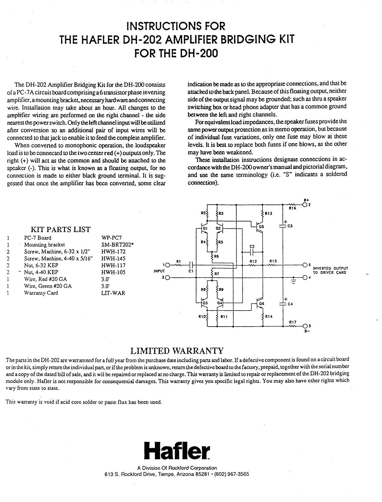
The Dl-l-ZOZ Amplifier Bridging Kit for the Did-200 consists
oia PC»7A circuitboard comprising a6 transistorphase inverting
arnplificr.amounting bracket, necessary hardwareand connecting
wire. Installation may take about an hour. All changes to the
amplifier wiring are performed on the right channel ~ the side
nearest the power switch. Only theleft channel input will beutilized
after conversion so an additional pair of input wires will be
connected to that jack to enable it to feed the complete amplifier.

When convened to monophonic operation, the loudspeaker
load is to beconnected to the two center red (+) outputs only. The
right (+) will act as the common and should be attached to the
speaker (-). This is what is known as a floating output. {or no
connection is made to either black ground terminal. It is sug-
gested that once the amplifier has been converted, some clear

KIT PARTS LIST
1 PC-7 Board WP-PC7
1 ' Mounting bracket SM-BRIZOT
2 Screw. Machine. 6-32 x 1/2" HWH-l72
2 Screw. Machine. 4-40 x 5/16" HWH-145
2 NuL 632 KEP HWH~117
2 Nut. 4-40 KEP HWH-lOS "m"
l Wire. Red #20 GA 3.0' 3
1 Wire. Green #20 GA 3.0
1 Warranty Card LIT-WAR

indication be made as to the appropriate connections, and that be
attached to the back panel. Because of this floating output. neither
sideof the outputsignal may be grounded; such as thru a speaker
switching box or head phone adapter that has a common ground
between the left and right channels.

For equivalentload impedances. the speaker fuses provide the
same power output protection as in stereo operation. but because
of individual {use variations, only one fuse may blow at these
levels. It is best to replace both fuses if one blows. as the other
may have been weakened. I

These installation instructions designate connections in ac-
cordance with the Dbl-200 owners manual and pictorial diagram.
and use the same terminology (i.e. "S" indicates a soldered
connection).

8+

6
INVERTED OUTPUT
TO DRIVER CARD
4

LIMITED WARRANTY

The parts in the DH-ZOZ are warrantecd for a full year from the purchase date including parts and labor. If a defective component is found on a circuit board
or in the kit. simply retum the individual part. or if the problem is unknown. return the defective board to the factory. prepaid. together with the serial number
and a copy of the dated bill of sale. and it wil be repaired or replaced at no charge. This warranty is limited to repair or replacement of the DH ~202 bridging
module only. Hafler is not responsible for consequential damages. This warranty gives you specific legal rights. You may also have other rights which

vary from state to state.

This warranty is void if acid corc solder or paste flux has been used.

Hafler

A Division Of Rockiord Corporation
613 8. Rockford Drive. Tempe. Arizona 85281 - (602) 967.3585

Page 2

DH-202 INSTALLATION INSTRUCTIONS

l. D Disconnect AC power from the DH-ZOO and remove all connect-

ing cables.

2. C] Remove 4 screws from the upper portion of the left output

module. and all of the 8 screws attaching the right output module
(the one near the power switch). Remove the amplifia cover. and
tilt the right module outwards for easier access.

3. D Disconnect the pair of twisted wires cormected to the right input

u-

as

\l

socket RS. The resistor may be left connected if you wish. but this
input will nomow be used. Unsolder this twisted pair fiom eyelets
l and 2 at the lop of the PC-6 output module. The reason these
wires will not simply be reconnected to PC-7A is that they may
be too heavy I gauge to fit into the eyelets on the new board.

. El Prepare one each red and green wires of the following lengths:

6-1/2".10".Ind11".TwistLhem togetherinpairs ofequal lengths.

. D Select the longest red/green pair and slip it under all of the wires

attached to the backpanel between the two input sockets. Connect
the green wire to the ground lug #1 of the left socket LS. (8-2).
Connect the red wire to lug #2. (3-2).

. D Select the shorter red/green pair andrplace it between the two

fuses FR near the center of the chassis alongside the transformer.
Connect the green wire to lug #2. which is class! to the center of
geztransfomter. (8-2). Connect the red wire to lug #4 beside it.

. El Select the two larger screws and nuts, and mount the bracket on

the rear fin of the right heat sink between the two transistors. with
the bracket bends next [0 the fins.

COMPONENT SIDE PC-7A
05
0-- RXH 05 .- R2
.- RID-e : ._ :2 _.A
.-m-. - RH
o-RlI-o Ao- RS-o vkufl
.- RS-e 0 12 .- 57..
.- Rfl-e
o-ct-a
I .- RG-o I
v-C4- 5&5"... V o-CH
1 or 1 or
v-- Rt7-- -- ins-a
. e o . c .
s 5 4 a z t

3. Cl With the smaller bolts, fasten the circuit board on the outside of
the bracket. with the components toward the rear of the amplifier.

9.D Using the remaining red/green pair, connect one green end to
eyelet #2 at the top towards the front of the P06 module. (S).
Connect the adjacent red wire to eyelet #1. (S). At the other end,
connect the green wire to eyelet #4 on the components side of PC-
7A. (5). The #1 eyelet is at the top of the PC-7A board. Connect
the red wire to eyelet #6. (5).

10.13 Select the shorter pair. which is connected to the fuses. Connect

the other end of the green wire to PC-7A eyelet #5. (S). Connect
the red wire to eyelet #2. (S).

.121 With the remaining pair from the left input socket. connect the
green wireto eyelet #3. (5). Connect the red wire to eyelet #1 , (S).

12. El Secure the output module to the chassis with 4 screws. You may
wish to leave them loose until the cover is installed. With the
module in position. place the input pair about 1/2" out from the
PC-6 board. straight down to the chassis. across the chassis and
underneath PC-7A. The pair from the fuses should likewise be
against the chassis. and in general all wires to those fuses should
be kept away from the PC-6 circuit board.

l3.D Install the cover and the remaining screws.

PC-7A PARTS LIST

R1 22.1K, 1%, metal film RMP/4-2212
R2 2.2K, l/4w. 5% carbon film RC/4-222
R3 2.2K, 1/4w. 5% carbon film RC/4-222
R4 47 ohms. 1/4w. 5% carbon film RC/4-47O
R5 47 ohms, l/4W. 5% carbon film RC/4-470
R6 8.2K. l/4w, 5% carbon film RC/Z-SZZ
R7 8.2K 1/4W. 5%, carbon film RCI'Z-SZZ
R8 47 ohms, l/4W. 5% carbon film RC/4-770
R9 47 ohms. 1/4). 5% carbon film RC/4-770
R10 2.2K. 1/4w, 5% carbon film RC/4-222
R11 2.2K. 1/4W, 5% carbon film RC/4»222
R12 22.1K. 1%, metal film RMP/4~2212
R13 100 ohms. l/4w. 5% carbon film RC/4-101
R14 100 ohms, 1l4w. 5% carbon film RC/4-101
R15 47 ohms, 1/4W. 5% carbon film RC/4-770
R16 3.3K, 1w. 5%. metal film RM1-332
R17 3.3K. 1w. 5%, metal film RMl-332
Cl lOmF. 16V. non-polarized CERNP-IOG
C2 6.8pF. IOOV dipped mica CM-068

C3 22mF. 25V. electrolytic CER-226AA
C4 22mF, 25V. electrolytic CER-226AA
Q1 BCSSOC NPN transistor SSH-650
Q2 BCSSOC NPN transistor SSH-650

Q3 BC560C PNP transistor SSH~651

Q4 BC560C PNP transistor SSH-651

Q5 MPSA63 PNP transistor SSH~695

Q6 MPSA13 NPN transistor SSH-645