Grundig Yacht Boy 10 WR 5401 Service Manual

This is the 12 pages manual for Grundig Yacht Boy 10 WR 5401 Service Manual.
Read or download the pdf for free. If you want to contribute, please mail your pdfs to info@audioservicemanuals.com.

Page: 1 / 12
left right
Grundig Yacht Boy 10 WR 5401 Service Manual

Extracted text from Grundig Yacht Boy 10 WR 5401 Service Manual (Ocr-read)


Page 1

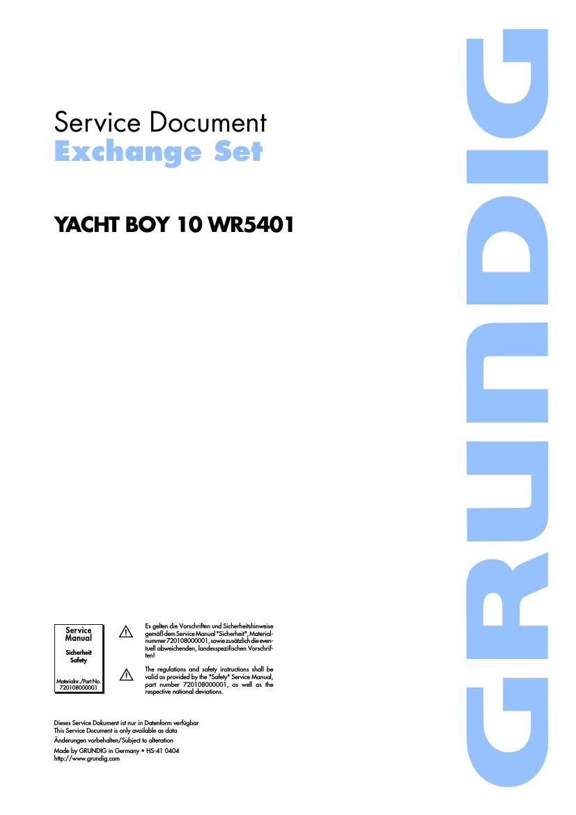
Service Document
Exchange SeI

YACHT BOY 'IO WR540'I

Service| A

Manua
Sicherheil
Safety

Materialnn/Put No. A
720103000001

Es gelten die Varsdtrilten and Sicherheilshitvweise
genial; dem Service Manual "Sidierlieit",Material-
nummer72010800000] , sowiezusfitzlidtdie even-
tuell abweichenden, landesspezilischen Vomlrrif-
Den!

The regulations and safety instructions shall be
valid as pawlded by the "Safety" Service Manual,
pan number 720108000001, as well as the
respective national deviations.

Dieses Service Dakument isl nur in Datenform verfiigbar
This Service Document is only available as data

Anderungen vorbehalten/Subiect to alteration
Made by GRUNDIG in Germany I HS-Afl 0404

http://www.gmndig.eom

GRUI'IDIG

Page 2

ALIGNMENT INSTRUCTIONS

(1) ALIGNMENT FOR FM FREQUENCY RANGE (2) ALIGNMENT FOR FM SENSITIVITY

a. Required Instruments

a. Required Instruments
FM/AM RF Signal Generator

FM RF signal generator

SSVM SSVM
b. Alignment Procedure b. Alignment Procedure
Mode Adjustment Procedure MOde Adjustment _ Procedure
(1) Set the power switch to the ON position. (1) Setthe power wish to the ON Desmon-
(2) Connect a SSVM to the TP5 and TP6. (g) 20: affix/II .° "le Speak?" in? .Tpel' . h d TP1
(3) Connect the FM signal generator to the input terminal of the rod antenna ( I Tagtec e signa genera or o e tnpu ermina 0 e ro an enna I '
(TP1' TP?) _ _ (4) Set the signal of the signal generator to the standard FM band, with frequency
L4 (4) Set the signal of the signal generator to the standard FM band, With frequency FM L3 deviation 0 22.5kHz modulation.
FM vcg deviation I0 .225 kHz modulation. _ VC2 (5) With the tuning gang fully closed, set the signal generator to 90 MHZ and
(5) With the tuning gang fully 0|0_sed. set the Signal generator 10 87-35 MHZ i015 adjust L3 (stretch or squeeze) for a maximum reading on the SSVM.
MHZ and adiusl L4 for a maXImum reading on the SSVM- (6) With the tuning gang fully open, set the signal generator to 106 MHZ and
(6) With the tuning gang fully open, set the signal generator to 108.25 MHz :025 adjust VCZ for a maximum reading on the SSVM.
MHZ and adjust V03 for a maximum reading on the SSVM. (7) Repeat steps 5 and 6 until the best sensitivity is obtained at both frequencies.
(7) Repeat Steps 5 and 6 until the best sensitivity is obtained at both frequencies.

c. Instrument Connection

0. Instrument Connection

Signal Generatoi SSVM

|:| IEI Sig nul GenerthI SSVM
.0
.9
J7

Test Point TPs El IE

Test Point TP1
<- Test Point TP6

(- .
Test Point TP5 Test Paint T P1

Test Point ml,

.0

(-
Test Point TP5 _?

Test Point ml, 7;,

GRunDIG YACHT BOY 'IO