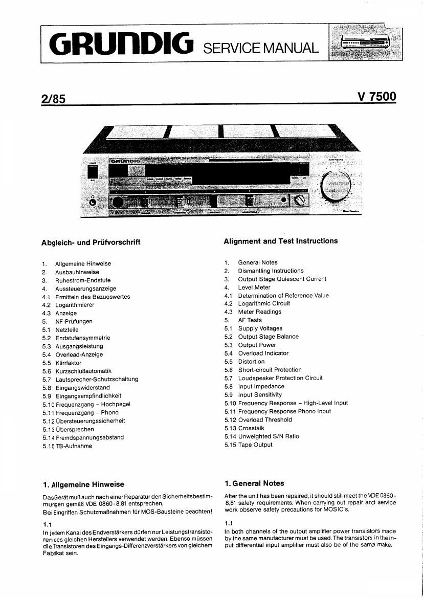
Grundig V 7500 Service Manual

This is the 12 pages manual for Grundig V 7500 Service Manual.
Read or download the pdf for free. If you want to contribute, please mail your pdfs to info@audioservicemanuals.com.

Page: 1 / 12
left right
Grundig V 7500 Service Manual

Extracted text from Grundig V 7500 Service Manual (Ocr-read)


Page 1

GRUDDIG SERVICE MANUAL

2/85

V 7500

Abgleich- und Priifvorschrift

1 Allgemeine Hinweise

2. Ausbauhinweise

3. Ruhestrom-Endstufe

4. Aussteuerungsanzeige

4.1 Ermitteln des Bezugswertes
4.2 Logarithmierer

4.3 Anzeige

5. NF-Prfifungen

5.1 Netzteile

5.2 Endstuiensymmetrie

5.3 Ausgangsleistung

5.4 Overiead-Anzeige

5.5 Klirrfaktor

5.6 KurzschluBautomatik

5.7 Lautsprecher-Schutzschaltung
5.8 Eingangswiderstand

5.9 Eingangsemptindlichkeit
5.10 Frequenzgang - Hochpegel
5.11 Frequenzgang - Phono
5.12 Ubersteuerungssicherheit
5.13 Ubersprechen

5.14 Fremdspannungsabstand
5.15 TB-Aufnahme

1. Allgemeine Hinweise

DasGerat muB auch nach einerReparatur den Slcherheitsbestim-
mungen gemaB VDE 0660-831 entsprechen.

Bei Eingritfen Schutzmalinahmen fur MOS-Bausteine beachten!

1 .1

ln iedem KanaI des Endverstarkers darfen nur Leistungstransisto-
ren des gleichen Herstellers venNendet werden. Ebenso mussen
die Transistoren des Eingangs-Differenzverstarkers von gleichem
Fabrikat sein.

Alignment and Test Instructions

1 General Notes

2, Dismantling Instructions

3. Output Stage Quiescent Current
4. Level Meter

4.1 Determination of Reference Value
4.2 Logarithmic Circuit

4.3 Meter Readings

5. AF Tests

5.1 Supply Voltages

5.2 Output Stage Balance

5.3 Output Power

5.4 Overload Indicator

5.5 Distortion

5.6 Short-circuit Protection

57 Loudspeaker Protection Circuit
58 Input Impedance

5.9 Input Sensitivity

5.10 Frequency Response - High»LeveI Input
5.11 Frequency Response Pnono Input
5.12 Overload Threshold

5.13 Crosstalk

5.14 Unweighted S/N Ratio

5.15 Tape Output

1. General Notes

After the unit has been repaired, it should still meet the VDE 0860 -
8,81 safety requirements. When carrying out repair and service
work observe safety precautions for MOSIC'S.

1.1

In both channels of the output amplifier power transistors made
by the same manufacturer must be used. The transistors in the in-
put differential input amplifier must also be of the same make.

Page 2

2. Ausbauhinweise

éflnen des Gerates

Vier Schrauben in den Seiten und eine Masseschraube auf
der Rflckseite des Gehauses herausdrehen

Gehause-Oberteil vorn anheben und nach hinten abnehmen.

2.1 Ausbau der NF/Netzteilplatte
Alle Steckverbindungen abziehen.
Zw6ll Schrauben herausdrehen.
Druckplatte nach oben hochklappen.

2.2 Ausbau der LS-Anschlqulatte. (Nach Ausbau der NF/
Netzteilplatte)

Drei Schrauben©herausdrehen. Anschlqulatte nach oben

herausnehmen.

2.3 Ausbau des Bedienteiles

Alle Steckverblndungen des Bedienteiles herausziehen.
Flint Schrauben @im Chassis-Boden herausdrehen.
Bedienteil nach 0 en abnehmen.

2.4 Ausbau der Reglerplatte. (Nach Ausbau des Bedienteiles)
Level-Drehknopf abziehen.

Zwei Schrauben im Bedienteil herausdrehen.
Regler-Druckplatte nach hinten herausziehen.

Bei Wiedereinbau der Regler-Druckplatte ist auf die Stellung der
vier Mitnehmer zu achten!

2.5 Ausbau der Anzeigeplatte. (Nach Ausbau der Regler-
Druckplatte)

Zwei Schrauben®herausdrehen Vor dern Abziehen der Tasten

sind alle Schalter auszulosen! Bruchgefahr der Rastmechanik!

Tasten mit Hilfe eines geeigneten Schraubendrehers ausrasten

Anzeige-Druckplatte nach hinten herausnehmen.

2. Dismantling Instructions

Opening the Unit

Undo the four screws ©at the sides and the earthing screw at
the back of the cabine .

Raise top part of cabinet at front and take off towards the hack.

2.1. Removal of the AF/Bower Supply Board
Undo all pluggable connections.

Remove 12 screws ®

Swing printed cicuit board upwards.

2.2 Removal of Loudspeaker Socket Board (After Removal of
AF/Power Supply Board)

Remove three screws ©. Lift out socket board.

2.3 Removal of Control Panel

Undo all pluggable connections to control board
Undo five screws in base.

Lift out control panel.

2.4 Removal of Control Board (After Removing Control Panel)

Pull off rotary level control.

Remove two screws @ in control panel,

Extract printed circuit control board towards rear.

N.B When reassembing see that drive pins are correctly posi»
tioned.

2.5 Removal of Meter Board (After removal of Printed Circuit
Control Board)

Undo two screws®

N.B. Before pulling off buttons. release all the switches (risk of
damage to latching mechansism).

Release buttons using a suitable screwdriver

Take out meter printed circuit board towards rear.

GR?
42m

1'
l-KUHLBLECH

1? ii
innnni-
.. 1..._ u

HEAT SINK